Fully Differential Op-Amp
An operational amplifier with a fully differential output signal, i.e. not grounded.
blockType: AcausalElectricPowerSystems.IntegratedCircuits.FullyDifferentialOperationalAmplifier
|
Path in the library: |
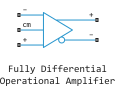
Description
Block Fully Differential Op-Amp simulates a fully differential operational amplifier. Differential signal transmission is preferable to asymmetric signal transmission because it is less susceptible to external noise sources. Applications include data acquisition where the input signals are differential, such as sigma-delta ADCs.
The following diagram shows the internal representation of the amplifier.

The parameters of the circuit components are determined by the specified block parameters. The gain of the two voltage-controlled voltage sources (VCVS1 and VCVS2) is set to half the value of the differential gain. Similarly, the rate of rise of each of the voltage sources is set to half the value of the maximum rate of rise of the output voltage. The voltages on the two output ports Vout+ and Vout− are limited to the specified minimum and maximum output voltages.
The output voltage at zero differential input voltage is controlled by the common-mode signal port cm. If the external circuit does not consume current from the cm port, then the output voltage is set equal to the average value of the positive and negative supply voltages using a ladder-type resistor circuit R3a and R3b. The negative supply voltage can be zero, which corresponds to operation in the absence of separate power supply. The values of the set minimum and maximum output voltages must correspond to the values of the set supply voltages. For example, the maximum value of the high output voltage will be less than the positive supply voltage, and the difference will correspond to the number of voltage drops at the p-n junctions in the circuit.
Assumptions and limitations
This block is a behavioral model of a fully differential operational amplifier. It does not take into account non-linear effects, such as the change in gain depending on the amplitude of the output voltage, as well as the non-linear nature of the dependence of the output voltage on the current at high load currents.
Ports
Conserving
#
+
—
non-inverting input port
electricity
Details
A non-directional electrical port connected to the non-inverting input of an operational amplifier.
| Program usage name |
|
#
-
—
inverting input port
electricity
Details
A non-directional electrical port connected to the inverting input of an operational amplifier.
| Program usage name |
|
#
cm
—
common-mode signal port
electricity
Details
A non-directional electrical port connected to the common-mode signal port of the operational amplifier. If this pin needs to be left open, connect the voltage sensor between the cm port and the reference port.
| Program usage name |
|
#
Vout-
—
inverting output port
electricity
Details
A non-directional electrical port connected to the inverting output of the operational amplifier.
| Program usage name |
|
#
Vout+
—
non-inverting output port
electricity
Details
A non-directional electrical port connected to the non-inverting output of the operational amplifier.
| Program usage name |
|
Parameters
Output Limits
#
Maximum output voltage high —
maximum high-level output voltage
V | uV | mV | kV | MV
Details
The maximum output voltage for either of the two output contacts relative to ground.
| Units |
|
| Default value |
|
| Program usage name |
|
| Evaluatable |
Yes |
#
Differential maximum slew rate —
maximum output voltage rise rate
V/s | V/us
Details
The maximum rate of rise of the output voltage of the differential operational amplifier.
| Units |
|
| Default value |
|
| Program usage name |
|
| Evaluatable |
Yes |
#
Output resistance —
output resistance
Ohm | mOhm | kOhm | MOhm | GOhm
Details
The output resistance of any of the outputs relative to the reference voltage of the common-mode signal. Therefore, the differential output resistance is twice the value of the output resistance. .
| Units |
|
| Default value |
|
| Program usage name |
|
| Evaluatable |
Yes |
#
Minimum output voltage low —
minimum low-level output voltage
V | uV | mV | kV | MV
Details
The minimum output voltage for either of the two output contacts relative to ground.
| Units |
|
| Default value |
|
| Program usage name |
|
| Evaluatable |
Yes |
Input Impedance
#
Differential input capacitance —
differential input capacity
F | pF | nF | uF | mF
Details
The input capacitance sensed by a current source connected between ports + and −.
| Units |
|
| Default value |
|
| Program usage name |
|
| Evaluatable |
Yes |
#
Common-mode input capacitance —
common-mode input capacity
F | pF | nF | uF | mF
Details
The input capacitance sensed by a current source connected between ground and port + or between ground and port −.
| Units |
|
| Default value |
|
| Program usage name |
|
| Evaluatable |
Yes |
#
Common-mode input resistance —
common-mode input resistance
Ohm | mOhm | kOhm | MOhm | GOhm
Details
The input resistance perceived by a voltage source connected between ground and port + or between ground and port −.
| Units |
|
| Default value |
|
| Program usage name |
|
| Evaluatable |
Yes |
#
Differential input resistance —
differential input resistance
Ohm | mOhm | kOhm | MOhm | GOhm
Details
The input resistance perceived by the voltage source connected between ports + and −.
| Units |
|
| Default value |
|
| Program usage name |
|
| Evaluatable |
Yes |
Gain
# Differential gain — Differential gain
Details
The gain applied to the voltage difference between the + and − ports.
| Default value |
|
| Program usage name |
|
| Evaluatable |
Yes |
#
Bandwidth —
bandwidth
Hz | kHz | MHz | GHz
Details
The frequency at which the differential voltage gain decreases by 3 dB compared to its value at direct current.
| Units |
|
| Default value |
|
| Program usage name |
|
| Evaluatable |
Yes |
Output Bias
#
Negative supply voltage —
negative supply voltage
V | uV | mV | kV | MV
Details
The value of the negative supply voltage connected to the common-mode bias resistor R3b (see block diagram).
| Units |
|
| Default value |
|
| Program usage name |
|
| Evaluatable |
Yes |
#
Common-mode port input resistance —
input resistance of the common-mode signal port
Ohm | mOhm | kOhm | MOhm | GOhm
Details
The input resistance perceived by a voltage source connected between ground and the common-mode signal port.
| Units |
|
| Default value |
|
| Program usage name |
|
| Evaluatable |
Yes |
#
Positive supply voltage —
positive supply voltage
V | uV | mV | kV | MV
Details
The value of the positive supply voltage connected to the common-mode bias resistor R3a (see block diagram).
| Units |
|
| Default value |
|
| Program usage name |
|
| Evaluatable |
Yes |
Initial Conditions
#
Initial differential output voltage —
initial differential output voltage
V | uV | mV | kV | MV
Details
The initial differential voltage between the two outputs at zero output current.
| Units |
|
| Default value |
|
| Program usage name |
|
| Evaluatable |
Yes |