Independent Suspension - Double Wishbone
Independent suspension on double wishbones.
blockType: SubSystem
|
Path in the library: |
Description
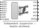
Block Independent Suspension - Double Wishbone Implements independent suspension on double wishbones for multiple axles with multiple wheels on each axle.
The block simulates the elasticity, damping, and geometric effects of the suspension as functions of the relative positions and speeds of the vehicle and the wheel hub, taking into account the compliance and damping parameters specific to each axle. Using data on suspension compliance and damping, the unit calculates the force exerted on the vehicle and wheel. The block uses a coordinate system with a downward pointing axis (defined in the SAE J670 standard). The following parameters can be configured for each suspension element:
-
For the axle — the number of wheels, the presence of a stabilizer bar for axles with two wheels, suspension parameters;
-
For the wheel, the angles of rotation.
The block contains spring elements that store energy and damping elements that dissipate energy. It does not contain mass elements that store energy. The block assumes that the vehicle blocks (sprung mass) and wheels (unsprung mass) connected to the block accumulate suspension energy related to the mass.
To simulate a vehicle with the following characteristics: two axles, two wheels on each axle, the angle of rotation for both wheels on the front axle and the stabilizer bar on the front axle, set the parameters:
-
Number of axles NumAxl meaning
2; -
Number of wheels per axle [NumWhlsByAxl] meaning
[2 2]; -
Steered axle enable by axle [StrgEnByAxl] meaning
[1 0]; -
Anti-sway axle enable by axle [AntiSwayEnByAxl] meaning
[1 0].
The block uses the wheel number for indexing input and output signals. The table below provides information about the wheel, axle and the corresponding wheel number for a vehicle with the following characteristics: two axles and two wheels on each axle.
| Wheel | The axis | Wheel number |
|---|---|---|
Front left |
The front |
|
Front right |
The front |
|
Rear left |
The back |
|
Rear right |
The back |
|
Suspension ductility and damping
The unit uses a linear spring and a damper to simulate the vertical dynamic effects of the suspension system. Using the relative positions and speeds of the vehicle and the wheel hub, the unit calculates the vertical suspension forces on the wheel and the vehicle. The unit uses a linear equation that relates vertical damping and ductility to the height of the suspension, the rate of change in suspension height, and the absolute value of the turning angles.
The block implements the following equation:
where
-
— suspension force applied to the numbered wheel on the axis along the axis , mounted on the wheel;
-
— the preload force of the vertical suspension spring applied to the wheels on the axle ;
-
— the stiffness coefficient of the vertical spring for the axes;
-
— movement and speed of the vehicle for the axis And the wheels along the inertial axis ;
-
— movement and speed of the wheel at the axis attachment point along the axis the inertial coordinate system;
-
— the angle of rotation of the wheel relative to the vector of force applied to the wheel hub;
-
— the input angle of rotation of the wheels for the axle And the wheels ;
-
— damping coefficient;
-
— the vertical force of the rigid stop on the axis and the wheel along the inertial axis ;
-
— vertical force from the stabilizer bar on the axis and the wheel along the axis the inertial coordinate system.
Damping coefficient depends on the parameter value Enable active damping. If this option is unchecked, the damping coefficient remains constant. , where — the coefficient of vertical damping of the wheel suspension on the axle . If this option is selected, an interpolation table is used, which is a function of the fill factor of the active damper and the drive speed.:
Within the framework of this block, it is assumed that the suspension elements have no mass. Therefore, the suspension forces and torques acting on the vehicle are equal to the suspension forces and torques acting on the wheel.
where
-
— the force and moment of suspension applied to the vehicle on the axle and the wheel along the axis , mounted on the wheel;
-
— the force and moment of suspension applied to the vehicle on the axle and the wheel along the axis , mounted on the wheel;
-
— the force and moment of suspension applied to the vehicle on the axle and the wheel along the axis , mounted on the wheel;
-
— the force and moment of suspension applied to the wheel under the number on the axis along the axis , mounted on the wheel;
-
— the force and moment of suspension applied to the wheel under the number on the axis along the axis , mounted on the wheel;
-
— the force and moment of suspension applied to the wheel under the number on the axis along the axis , mounted on the wheel;
-
and — effective wheel radius for the axle And the wheels along the axes and accordingly;
-
— suspension height for the axle And the wheels .
The unit sets the wheel positions and speeds equal to the transverse and longitudinal positions and speeds of the vehicle.
where
-
— movement and speed of the wheel on the axis along the inertial axis ;
-
— movement and speed of the vehicle on the axle and the wheel along the inertial axis ;
-
— wheel movement and speed on the axis along the inertial axis ;
-
— movement and speed of the vehicle on the axle and the wheel along the inertial axis .
The forces of the stops
Thrust feedback force which is applied in the block depends on whether the suspension is compressed or stretched. The force arises:
-
during compression, when the suspension is compressed by more than the maximum value set by the parameter Suspension maximum height Hmax, m;
-
when stretched, when the suspension is stretched by more than the maximum value set by the parameter Suspension maximum height Hmax, m.
The stiffness coefficient based on hyperbolic tangent and exponential scaling is used to calculate the force in the block.
Stabilizer bar
Optionally, you can use the parameter Anti-sway axle enable by axle [AntiSwayEnByAxl], which allows to activate the stabilizer bar for each axle with two wheels. The figure below shows how the stabilizer bar transmits torque between two wheels of an independent suspension on a common axle. Each independent suspension transmits torque to the stabilizer bar through a lever that connects the stabilizer bar to the independent suspension.
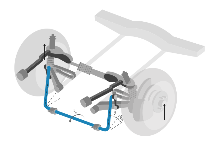
To calculate the force acting on the stabilizer bar, the unit uses the following equations:
-
Angular deviation of the stabilizer bar for this axis And the wheels :
where
-
— the initial angle of rotation of the stabilizer bar;
-
— the vertical distance from the mounting point of the stabilizer bar to the center line of the stabilizer;
-
— the radius of the stabilizer bar.
-
-
Angle of rotation of the stabilizer bar :
-
Torque of the stabilizer bar :
-
The forces of the stabilizer applied to the wheel on the axis along the axis , mounted on the wheel:
where
-
— moving the vehicle on the axle and the wheel along the inertial axis ;
-
— movement and speed of the wheel on the axis along the inertial axis .
-
Angles of camber, longitudinal tilt of the axis of rotation of the wheel and convergence
The unit uses linear functions of suspension height and angle of rotation to calculate camber angles, longitudinal tilt of the wheel axis and convergence.
where
-
— the camber angle of the wheel on the axle and the wheel ;
-
— the angle of the longitudinal inclination of the axis of rotation of the wheel on the axis and the wheel ;
-
— the angle of convergence of the wheel on the axle and the wheel ;
-
, , — nominal angles of camber, tilt and convergence (respectively) of the axis suspension at zero angle of rotation;
-
, , — the dependence of the angles of camber, tilt and convergence, respectively, on the height of the suspension for the axle ;
-
, , — the dependence of the angles of collapse, tilt and convergence, respectively, on the angle of rotation for the axis ;
-
— the dependence of the rotation angle on the vertical force for the axis ;
-
— input rotation angle for the axis And the wheels ;
-
— moving the vehicle on the axle and the wheel along the inertial axis ;
-
— moving the wheel on the axis along the inertial axis .
Wheel rotation angles
Optionally, you can use the parameter Steered axle enable by axle [StrgEnByAxl], which allows you to set the rotation angles. To calculate the rotation angles, the unit shifts the set rotation angles using a linear function of the suspension height.:
where
-
— dependence of the angle of convergence of the axis from the angle of rotation;
-
— dependence of the axis rotation angle from the tilt of the vertical force;
-
— dependence of the angle of convergence of the axis from the height of the suspension;
-
— the angle of rotation of the wheel for the axle And the wheels ;
-
— input rotation angle for the axis And the wheels ;
-
— moving the vehicle on the axle and the wheel along the inertial axis ;
-
— moving the wheel on the axis along the inertial axis .
Power and energy
The unit calculates these suspension characteristics for each axle And the wheels :
-
Power dissipation :
where — the angle of rotation for the axis And the wheels ;
-
Absorbed energy :
-
Suspension height :
where
-
— movement and speed of the vehicle on the axle and the wheel along the inertial axis ;
-
— movement and speed of the wheel on the axis along the inertial axis ;
-
— the preload force of the vertical suspension spring applied to the wheels on the axle ;
-
— the angle of rotation relative to the vertical force applied to the wheel hubs on the axle .
-
-
The distance from the center of the wheel hub to the point of contact of the tire with the road:
where — effective wheel radius on the axis from the center of the wheel hub to the point of contact of the tire with the road.
Ports
Input
WhlPz
# —
moving the wheel along the axis
+
array
Details
Moving the wheel along the axis , mounted on a wheel, measured in meters. Size of the array: 1 for the total number of wheels on the vehicle.
For example, for a two-axle vehicle with two wheels on each axle, the signal array WhlPz has the size 1 on 4:
| Wheel | Array element | The axis | Wheel number |
|---|---|---|---|
Front left |
|
|
|
Front right |
|
|
|
Rear left |
|
|
|
Rear right |
|
|
|
| Data types |
|
| Complex numbers support |
No |
WhlRe
# —
effective wheel radius
array
Details
Effective wheel radius , measured in meters. Size of the array: 1 for the total number of wheels on the vehicle.
For example, for a two-axle vehicle with two wheels on each axle, the signal array WhlRe has the size 1 on 4:
| Wheel | Array element | The axis | Wheel number |
|---|---|---|---|
Front left |
|
|
|
Front right |
|
|
|
Rear left |
|
|
|
Rear right |
|
|
|
| Data types |
|
| Complex numbers support |
No |
# WhlVz —
the speed of rotation of the wheel on the axis
+ `array`
Details
Wheel speed along the axis , mounted on the wheel, measured in m/s. Size of the array: 1 for the total number of wheels on the vehicle.
For example, for a two-axle vehicle with two wheels on each axle, the signal array WhlVz has the size 1 on 4:
| Wheel | Array element | The axis | Wheel number |
|---|---|---|---|
Front left |
|
|
|
Front right |
|
|
|
Rear left |
|
|
|
Rear right |
|
|
|
| Data types |
|
| Complex numbers support |
No |
WhlFx
# —
the longitudinal force acting on the wheel of the vehicle
+
array
Details
Longitudinal force acting on the vehicle along the inertial axis . Size of the array: 1 for the total number of wheels on the vehicle.
For example, for a two-axle vehicle with two wheels on each axle, the WhlFx signal array has the size 1 on 4:
| Wheel | Array element | The axis | Wheel number |
|---|---|---|---|
Front left |
|
|
|
Front right |
|
|
|
Rear left |
|
|
|
Rear right |
|
|
|
| Data types |
|
| Complex numbers support |
No |
WhlFy
# —
the lateral force acting on the wheel of the vehicle
+
array
Details
Transverse force acting on the vehicle along the inertial axis . Size of the array: 1 for the total number of wheels on the vehicle.
For example, for a two-axle vehicle with two wheels on each axle, the signal array WhlFy has the size 1 on 4:
| Wheel | Array element | The axis | Wheel number |
|---|---|---|---|
Front left |
|
|
|
Front right |
|
|
|
Rear left |
|
|
|
Rear right |
|
|
|
| Data types |
|
| Complex numbers support |
No |
WhlM
# —
the moment acting on the wheel from the suspension side
+
array
Details
Longitudinal, transverse and vertical moments on the axis and the wheel , acting on the wheel from the suspension side in the reference coordinate of the wheel hub, measured in nm. Size of the array: 3 the number of wheels on the vehicle.
-
WhlM[1,…]— the moment acting on the wheel from the suspension side along the inertial axis (longitudinal); -
WhlM[2,…]— the moment acting on the wheel from the suspension side along the inertial axis (transverse); -
WhlM[3,…]— the moment acting on the wheel from the suspension side along the inertial axis (vertical).
For example, for a two-axle vehicle with two wheels on each axle, an array of WhlM signals:
-
It has a size
3on4; -
It contains the moments acting on the four wheels from the suspension side in accordance with the location of the axles and wheels:
Wheel Array element The axis Wheel number The axis of the moment Front left
WhlM[1, 1]11The inertial axis (longitudinal)
Front right
WhlM[1, 2]12Rear left
WhlM[1, 3]21Rear right
WhlM[1, 4]22Front left
WhlM[2, 1]11The inertial axis (transverse)
Front right
WhlM[2, 2]12Rear left
WhlM[2, 3]21Rear right
WhlM[2, 4]22Front left
WhlM[3, 1]11The inertial axis (vertical)
Front right
WhlM[3, 2]12Rear left
WhlM[3, 3]21Rear right
WhlM[3, 4]22
| Data types |
|
| Complex numbers support |
No |
VehP
# —
moving the vehicle
+
array
Details
Moving the vehicle away from the axle And the wheels along the inertial coordinate system, measured in meters. The size of the input data array: 3 the number of wheels on the vehicle.
-
VehP[1,…]— moving moving the vehicle away from the wheel along the inertial axis ; -
VehP[2,…]— moving moving the vehicle away from the wheel along the inertial axis ; -
VehP[3,…]— moving moving the vehicle away from the wheel along the inertial axis .
For example, for a two-axle vehicle with two wheels on each axle, an array of VehP signals:
-
Has a size of
3on4; -
It contains four movements according to the position of the axles and wheels:
Wheel Array element The axis Wheel number The axis Front left
VehP[1, 1]11The inertial axis
Front right
VehP[1, 2]12Rear left
VehP[1, 3]21Rear right
VehP[1, 4]22Front left
VehP[2, 1]11The inertial axis
Front right
VehP[2, 2]12Rear left
VehP[2, 3]21Rear right
VehP[2, 4]22Front left
VehP[3, 1]11The inertial axis
Front right
VehP[3, 2]12Rear left
VehP[3, 3]21Rear right
VehP[3, 4]22
| Data types |
|
| Complex numbers support |
No |
VehV
# —
vehicle speed
+
array
Details
Vehicle speed on the axle and the wheel along the inertial coordinate system, measured in m/s. The size of the input data array: 3 the number of wheels on the vehicle.
-
VehV[1,…]— speed vehicle wheels along the inertial axis ; -
VehV[2,…]— speed vehicle wheels along the inertial axis ; -
VehV[3,…]— speed vehicle wheels along the inertial axis .
For example, for a two-axle vehicle with two wheels on each axle, an array of VehV signals:
-
It has a size
3on4; -
It contains four speeds according to the position of the axles and wheels:
Wheel Array element The axis Wheel number The axis Front left
VehV[1, 1]11The inertial axis
Front right
VehV[1, 2]12Rear left
VehV[1, 3]21Rear right
VehV[1, 4]22Front left
VehV[2, 1]11The inertial axis
Front right
VehV[2, 2]12Rear left
VehV[2, 3]21Rear right
VehV[2, 4]22Front left
VehV[3, 1]11The inertial axis
Front right
VehV[3, 2]12Rear left
VehV[3, 3]21Rear right
VehV[3, 4]22
| Data types |
|
| Complex numbers support |
No |
StrgAng
# —
optional rotation angle
array
Details
Optional rotation angle for each wheel. Size of the input array: 1 the number of steerable wheels.
For example, for a two-axle vehicle with two wheels on each axle, you can enter the turning angles for both wheels on the first axle.:
-
The input data array has the size
1on2; -
The StrgAng signal array contains two rotation angles according to the position of the axles and wheels:
Wheel Array element The axis Wheel number Front left
StrgAng[1, 1]11Front right
StrgAng[1, 2]12
Dependencies
To use the StrgAng port, set the parameter Steered axle enable by axle [StrgEnByAxl] meaning [1 0].
| Data types |
|
| Complex numbers support |
No |
Output
Info
# —
information signal
+
the tire
Details
The bus signal containing the block values. The signals are arrays that depend on the position of the wheel.
For example, these are indexes for a two-axle vehicle with two wheels. The total number of wheels is four.
-
One-dimensional array of signals (
1on4)Wheel Array element The axis Wheel number Front left
[1, 1]11Front right
[1, 2]12Rear left
[1, 3]21Rear right
[1, 4]22 -
Three-dimensional array of signals (
3on4)Wheel Array element The axis Wheel number Front left
[1, 1]11Front right
[1, 2]12Rear left
[1, 3]21Rear right
[1, 4]22Front left
[2, 1]11Front right
[2, 2]12Rear left
[2, 3]21Rear right
[2, 4]22Front left
[3, 1]11Front right
[3, 2]12Rear left
[3, 3]21Rear right
[3, 4]22
| The signal | Description | Array of signals | Variable | Units of measurement |
|---|---|---|---|---|
|
Wheel tilt angles depending on the location of the axle and wheel |
One-dimensional |
|
glad |
|
|
|||
|
|
|||
|
Suspension height |
One-dimensional |
|
m |
|
Dissipated suspension power |
One-dimensional |
|
Tue |
|
Absorbed suspension energy |
One-dimensional |
|
J |
VehF |
Forces acting on the vehicle from the suspension side |
Three-dimensional |
For a two-axle vehicle with two wheels on the axle: |
N |
VehM |
The moments acting on the vehicle from the suspension side |
Three-dimensional |
For a two-axle vehicle with two wheels on the axle: |
N⋅m |
WhlF |
Force acting on the wheel from the suspension side |
Three-dimensional |
For a two-axle vehicle with two wheels on the axle: |
N |
WhlP |
Moving the wheel |
Three-dimensional |
For a two-axle vehicle with two wheels on the axle: |
m |
WhlV |
Wheel speed |
Three-dimensional |
For a two-axle vehicle with two wheels on the axle: |
m/s |
WhlAng |
Angles of camber, tilt and convergence of the wheel |
Three-dimensional |
For a two-axle vehicle with two wheels on the axle: |
glad |
| Data types |
|
| Complex numbers support |
No |
VehF
# —
the force acting on the vehicle from the suspension side
+
array
Details
Longitudinal, transverse and vertical forces on the axis and the wheel , acting on the vehicle from the suspension side at the suspension junction point, measured in Newtons. Size of the array: 3 the number of wheels on the vehicle.
-
VehF[1,…]— the force acting on the vehicle from the suspension side along the inertial axis (longitudinal); -
VehF[2,…]— the force acting on the vehicle from the suspension side along the inertial axis (transverse); -
VehF[3,…]— the force acting on the vehicle from the suspension side along the inertial axis (vertical).
For example, for a two-axle vehicle with two wheels on each axle, an array of VehF signals:
-
It has a size
3on4; -
It contains forces acting on the vehicle from the suspension side in accordance with the location of the axles and wheels:
Wheel Array element The axis Wheel number The axis of power Front left
VehF[1, 1]11The inertial axis (longitudinal)
Front right
VehF[1, 2]12Rear left
VehF[1, 3]21Rear right
VehF[1, 4]22Front left
VehF[2, 1]11The inertial axis (transverse)
Front right
VehF[2, 2]12Rear left
VehF[2, 3]21Rear right
VehF[2, 4]22Front left
VehF[3, 1]11The inertial axis (vertical)
Front right
VehF[3, 2]12Rear left
VehF[3, 3]21Rear right
VehF[3, 4]22
| Data types |
|
| Complex numbers support |
No |
VehM
# —
the moment acting on the vehicle from the suspension side
+
array
Details
Longitudinal, transverse and vertical moments on the axis and the wheel , acting on the vehicle from the suspension side at the suspension connection point, measured in Nm. Size of the array: 3 the number of wheels on the vehicle.
-
VehM[1,…]— the moment acting on the vehicle from the suspension side along the inertial axis (longitudinal); -
VehM[2,…]— the moment acting on the vehicle from the suspension side along the inertial axis (transverse); -
VehM[3,…]— the moment acting on the vehicle from the suspension side along the inertial axis (vertical).
For example, for a two-axle vehicle with two wheels on each axle, an array of VehM signals:
-
It has a size
3on4; -
It contains the moments acting on the vehicle from the suspension side in accordance with the location of the axles and wheels:
Wheel Array element The axis Wheel number The axis of the moment Front left
VehM[1, 1]11The inertial axis (longitudinal)
Front right
VehM[1, 2]12Rear left
VehM[1, 3]21Rear right
VehM[1, 4]22Front left
VehM[2, 1]11The inertial axis (transverse)
Front right
VehM[2, 2]12Rear left
VehM[2, 3]21Rear right
VehM[2, 4]22Front left
VehM[3, 1]11The inertial axis (vertical)
Front right
VehM[3, 2]12Rear left
VehM[3, 3]21Rear right
VehM[3, 4]22
| Data types |
|
| Complex numbers support |
No |
WhlF
# —
force acting on the wheel from the suspension side
array
Details
Longitudinal, transverse and vertical forces on the axis and the wheel , acting on the wheel from the suspension side in the reference coordinate of the wheel hub, measured in Newtons. Size of the array: 3 the number of wheels on the vehicle.
-
WhlF[1,…]— the force acting on the wheel from the suspension side along the inertial axis (longitudinal); -
WhlF[2,…]— the force acting on the wheel from the suspension side along the inertial axis (transverse); -
WhlF[3,…]— the force acting on the wheel from the suspension side along the inertial axis (vertical).
For example, for a two-axle vehicle with two wheels on each axle, an array of WhlF signals:
-
Has a size of
3on4; -
It contains the forces acting on the wheel from the suspension side in accordance with the location of the axles and wheels:
Wheel Array element The axis Wheel number The axis of power Front left
WhlF[1, 1]11The inertial axis (longitudinal)
Front right
WhlF[1, 2]12Rear left
WhlF[1, 3]21Rear right
WhlF[1, 4]22Front left
WhlF[2, 1]11The inertial axis (transverse)
Front right
WhlF[2, 2]12Rear left
WhlF[2, 3]21Rear right
WhlF[2, 4]22Front left
WhlF[3, 1]11The inertial axis (vertical)
Front right
WhlF[3, 2]12Rear left
WhlF[3, 3]21Rear right
WhlF[3, 4]22
| Data types |
|
| Complex numbers support |
No |
WhlV
# —
wheel rotation speed
array
Details
Longitudinal, transverse and vertical rotation speeds of the wheel on the axis , measured in m/s. Size of the array: 3 the number of wheels on the vehicle.
-
WhlV[1,…]— the speed of rotation of the wheel along the inertial axis (longitudinal); -
WhlV[2,…]— the speed of rotation of the wheel along the inertial axis (transverse); -
WhlV[3,…]— the speed of rotation of the wheel along the inertial axis (vertical).
For example, for a two-axle vehicle with two wheels on each axle, an array of WhlV signals:
-
Has a size of
3on4; -
Contains the rotation speeds of the wheel according to the position of the axles and wheels:
Wheel Array element The axis Wheel number The axis of power Front left
WhlV[1, 1]11The inertial axis (longitudinal)
Front right
WhlV[1, 2]12Rear left
WhlV[1, 3]21Rear right
WhlV[1, 4]22Front left
WhlV[2, 1]11The inertial axis (transverse)
Front right
WhlV[2, 2]12Rear left
WhlV[2, 3]21Rear right
WhlV[2, 4]22Front left
WhlV[3, 1]11The inertial axis (vertical)
Front right
WhlV[3, 2]12Rear left
WhlV[3, 3]21Rear right
WhlV[3, 4]22
| Data types |
|
| Complex numbers support |
No |
WhlAng
# —
angles of camber, tilt and convergence of the wheel
array
Details
Angles of camber, tilt and convergence of the wheel on the axle and the wheel , measured in radians. Size of the array: 3 the number of wheels on the vehicle.
-
WhlAng[1,…]— camber angle; -
WhlAng[2,…]— tilt angle; -
WhlAng[3,…]— angle of convergence.
For example, for a two-axle vehicle with two wheels on each axle, an array of WhlAng signals:
-
Has a size of
3on4; -
Contains angles according to the position of the axles and wheels:
Wheel Array element The axis Wheel number Corner Front left
WhlAng[1, 1]11Camber Angle
Front right
WhlAng[1, 2]12Rear left
WhlAng[1, 3]21Rear right
WhlAng[1, 4]22Front left
WhlAng[2, 1]11Tilt Angle (Caster)
Front right
WhlAng[2, 2]12Rear left
WhlAng[2, 3]21Rear right
WhlAng[2, 4]22Front left
WhlAng[3, 1]11Angle of Convergence (Toe)
Front right
WhlAng[3, 2]12Rear left
WhlAng[3, 3]21Rear right
WhlAng[3, 4]22
| Data types |
|
| Complex numbers support |
No |
Parameters
Main group
# Enable active damping — enable damping
Details
Enable damping.
Dependencies
After checking this box, the options appear:
-
Damping coefficient map [f_act_susp_cz], Ns/m;
-
Damping actuator duty cycle breakpoints [f_act_susp_duty_bpt];
-
Damping actuator velocity breakpoints [f_act_susp_zdot_bpt], m/s.
| Default value |
|
| Program usage name |
|
| Tunable |
No |
| Evaluatable |
Yes |
# Number of axles NumAxl — number of axes
Details
Number of axes , a dimensionless parameter.
| Default value |
|
| Program usage name |
|
| Tunable |
No |
| Evaluatable |
Yes |
# Number of wheels per axle [NumWhlsByAxl] — number of wheels per axle
Details
Number of wheels per axle , a dimensionless parameter. The vector is equal to the value 1 multiplied by the number of axes the vehicle. For example, [1, 2] indicates one wheel on the first axle and two wheels on the second axle.
| Default value |
|
| Program usage name |
|
| Tunable |
No |
| Evaluatable |
Yes |
# Steered axle enable by axle [StrgEnByAxl] — a logical vector for activating axis control
Details
A logical dimensionless vector , which activates the axis control. The vector is equal to the value 1 multiplied by the number of axes the vehicle. For example, for a two-axle vehicle, the value:
-
[1 0]— activates axis 1 control and disables axis 2 control; -
[1 1]— activates the control of axes 1 and 2.
Dependencies
When setting the value for this parameter 1:
-
The StrgAng port is activated.
-
The following parameters appear:
-
Toe angle vs steering angle slope ToeStrgSlp;
-
Caster angle vs steering angle slope CasterStrgSlp;
-
Camber angle vs steering angle slope CamberStrgSlp;
-
Suspension height vs steering angle slope StrgHgtSlp, m/rad.
-
For example, for a two-axle vehicle with two wheels on each axle, you can enter the turning angles for both wheels on the first axle.:
-
To use the StrgAng port, set the parameter Steered axle enable by axle [StrgEnByAxl] meaning
[1 0]. The input data array has the size1on2. -
The StrgAng signal array contains two rotation angles according to the position of the axles and wheels:
Wheel Array element The axis Wheel number Front left
StrgAng[1, 1]11Front right
StrgAng[1, 2]12
| Default value |
|
| Program usage name |
|
| Tunable |
No |
| Evaluatable |
Yes |
# Anti-sway axle enable by axle [AntiSwayEnByAxl] — a logical vector for activating axis stabilization
Details
A logical dimensionless vector that activates axis stabilization . For example, the value [1 0] activates axis 1 stabilization and disables axis 2 stabilization. The vector is equal to 1 multiplied by the number of axes the vehicle.
Dependencies
When setting the value for this parameter 1 The following parameters appear:
-
Anti-sway arm radius AntiSwayR, m;
-
Anti-sway arm neutral angle AntiSwayNtrlAng, rad;
-
Anti-sway torsion spring constant AntiSwayTrsK, Nm/rad.
| Default value |
|
| Program usage name |
|
| Tunable |
No |
| Evaluatable |
Yes |
Compliance and damping
# Suspension spring constant Kz, N/m — stiffness coefficient of the suspension spring
Details
Linear stiffness coefficient vertical springs for independent suspension wheels on the axle , measured in N/m.
The vector is equal to the value 1 multiplied by the number of axes the vehicle. If you specify a scalar value, the block uses this value for all axes.
| Default value |
|
| Program usage name |
|
| Tunable |
No |
| Evaluatable |
Yes |
# Suspension spring preload F0z, N — preload on suspension springs
Details
Vertical force the preload of the springs applied to the wheels on the axle in the reference coordinates of the wheel hub, measured in Newtons. Positive preload forces:
-
Causing the vehicle to lift;
-
Directed along the negative inertial axis .
The vector is equal to the value 1 multiplied by the number of axes the vehicle. If you specify a scalar value, the block uses this value for all axes.
| Default value |
|
| Program usage name |
|
| Tunable |
No |
| Evaluatable |
Yes |
# Suspension shock damping constant Cz, Ns/m — damping coefficient of suspension shock absorbers
Details
Linear coefficient vertical damping for independent suspension wheels on the axle , measured in N⋅s/m .
The vector is equal to the value 1 multiplied by the number of axes the vehicle. If you specify a scalar value, the block uses this value for all axes.
Dependencies
To use this option, uncheck the box. Enable active damping.
| Default value |
|
| Program usage name |
|
| Tunable |
No |
| Evaluatable |
Yes |
# Suspension maximum height Hmax, m — maximum suspension height
Details
Maximum suspension extension or minimum suspension compression height for the axis before the suspension reaches a rigid stop, measured in meters.
The vector is equal to the value 1 multiplied by the number of axes the vehicle. If you specify a scalar value, the block uses this value for all axes.
| Default value |
|
| Program usage name |
|
| Tunable |
No |
| Evaluatable |
Yes |
Active damping
# Damping coefficient map [f_act_susp_cz], Ns/m — interpolation table of the fill factor
Details
Table of damping coefficients as a function of the active filling factor and the compression rate of the drive, in N⋅s/m. Each value determines the damping for a specific combination of fill factor and drive speed. The dimensions of the array must correspond to the dimensions of the vector of reference points of the fill factor. and drive speeds .
Dependencies
To use this option, uncheck the box. Enable active damping.
| Default value |
|
| Program usage name |
|
| Tunable |
No |
| Evaluatable |
Yes |
# Damping actuator duty cycle breakpoints [f_act_susp_duty_bpt] — fill factor reference points
Details
Reference points of the fill factor of the damping drive, a dimensionless parameter.
Dependencies
To use this option, uncheck the box. Enable active damping.
| Default value |
|
| Program usage name |
|
| Tunable |
No |
| Evaluatable |
Yes |
# Damping actuator velocity breakpoints [f_act_susp_zdot_bpt], m/s — speed reference points
Details
Reference points of the damping drive speed, measured in m/s.
Dependencies
To use this option, uncheck the box. Enable active damping.
| Default value |
|
| Program usage name |
|
| Tunable |
No |
| Evaluatable |
Yes |
Geometry settings and effects
# Toe angle at steering center Toe, rad — angle of convergence
Details
Nominal angle suspension convergence at zero angle of rotation, measured in radians.
| Default value |
|
| Program usage name |
|
| Tunable |
No |
| Evaluatable |
Yes |
# Roll steer angle vs suspension height slope RollStrgSlp, rad/m — angle of rotation of the suspension
Details
Angle of rotation depending on the height of the suspension, measured in rad/m.
The vector is equal to the value 1 multiplied by the number of axes the vehicle. If you specify a scalar value, the block uses this value for all axes.
| Default value |
|
| Program usage name |
|
| Tunable |
No |
| Evaluatable |
Yes |
# Toe angle vs steering angle slope ToeStrgSlp — the angle of convergence depends on the angle of rotation of the wheel
Details
Wheel convergence angle depending on the angle of rotation, a dimensionless parameter.
The vector is equal to the value 1 multiplied by the number of axes the vehicle. If you specify a scalar value, the block uses this value for all axes.
Dependencies
To use the StrgAng port, set the parameter Steered axle enable by axle [StrgEnByAxl] meaning 1.
| Default value |
|
| Program usage name |
|
| Tunable |
No |
| Evaluatable |
Yes |
# Caster angle at steering center Caster, rad — the angle of the axis of rotation of the wheel in the center of the wheel
Details
Nominal tilt angle the axis of rotation of the wheel at zero angle of rotation, measured in radians.
| Default value |
|
| Program usage name |
|
| Tunable |
No |
| Evaluatable |
Yes |
# Caster angle vs suspension height slope CasterHslp, rad/m — the angle of inclination of the axis of rotation of the wheel depending on the height of the suspension
Details
Tilt angle the axis of rotation of the wheel depends on the height of the suspension, measured in rad/m.
The vector is equal to the value 1 multiplied by the number of axes the vehicle. If you specify a scalar value, the block uses this value for all axes.
| Default value |
|
| Program usage name |
|
| Tunable |
No |
| Evaluatable |
Yes |
# Caster angle vs steering angle slope CasterStrgSlp — the angle of inclination of the axis of rotation of the wheel depending on the angle of rotation of the wheel
Details
Tilt angle the axis of rotation of the wheel depends on the angle of rotation, a dimensionless parameter.
The vector is equal to the value 1 multiplied by the number of axes the vehicle. If you specify a scalar value, the block uses this value for all axes.
Dependencies
To use the StrgAng port, set the parameter Steered axle enable by axle [StrgEnByAxl] meaning 1.
| Default value |
|
| Program usage name |
|
| Tunable |
No |
| Evaluatable |
Yes |
# Camber angle at steering center Camber, rad — camber angle in the center of the wheel
Details
Nominal camber angle suspension at zero angle of rotation, measured in radians.
| Default value |
|
| Program usage name |
|
| Tunable |
No |
| Evaluatable |
Yes |
# Camber angle vs suspension height slope CamberHslp, rad/m — camber angle depending on suspension height
Details
Camber angle depending on the height of the suspension, measured in rad/m.
The vector is equal to the value 1 multiplied by the number of axes the vehicle. If you specify a scalar value, the block uses this value for all axes.
| Default value |
|
| Program usage name |
|
| Tunable |
No |
| Evaluatable |
Yes |
# Camber angle vs steering angle slope CamberStrgSlp — camber angle depending on the angle of rotation of the wheel
Details
Camber angle depending on the angle of rotation, a dimensionless parameter.
The vector is equal to the value 1 multiplied by the number of axes the vehicle. If you specify a scalar value, the block uses this value for all axes.
Dependencies
To use the StrgAng port, set the parameter Steered axle enable by axle [StrgEnByAxl] meaning 1.
| Default value |
|
| Program usage name |
|
| Tunable |
No |
| Evaluatable |
Yes |
# Suspension height vs steering angle slope StrgHgtSlp, m/rad — suspension height depending on the angle of rotation of the wheel
Details
Deviation of the rotation angle of the vertical force applied to the bearing point of the suspension wheel hub, measured in m/rad.
The vector is equal to the value 1 multiplied by the number of axes the vehicle. If you specify a scalar value, the block uses this value for all axes.
Dependencies
To use the StrgAng port, set the parameter Steered axle enable by axle [StrgEnByAxl] meaning 1.
| Default value |
|
| Program usage name |
|
| Tunable |
No |
| Evaluatable |
Yes |
Anti-sway parameters
# Anti-sway arm radius AntiSwayR, m — radius of the stabilizer bar
Details
Radius the lever of the stabilizer bar, measured in meters.
The vector is equal to the value 1 multiplied by the number of axes the vehicle. If you specify a scalar value, the block uses this value for all axes.
Dependencies
When setting the value for this parameter 1 The following parameters appear:
-
Anti-sway arm neutral angle AntiSwayNtrlAng, rad;
-
Anti-sway torsion spring constant AntiSwayTrsK, Nm/rad.
| Default value |
|
| Program usage name |
|
| Tunable |
No |
| Evaluatable |
Yes |
# Anti-sway arm neutral angle AntiSwayNtrlAng, rad — neutral angle of the stabilizer bar
Details
Neutral angle the lever of the stabilizer bar at the nominal height of the suspension, measured in radians.
The vector is equal to the value 1 multiplied by the number of axes the vehicle. If you specify a scalar value, the block uses this value for all axes.
Dependencies
When setting the value for this parameter 1 The following parameters appear:
-
Anti-sway arm radius AntiSwayR, m;
-
Anti-sway torsion spring constant AntiSwayTrsK, Nm/rad.
| Default value |
|
| Program usage name |
|
| Tunable |
No |
| Evaluatable |
Yes |
# Anti-sway torsion spring constant AntiSwayTrsK, Nm/rad — torsional stiffness of the stabilizer bar
Details
Torsional rigidity stabilizer bar, measured in nm/rad.
The vector is equal to the value 1 multiplied by the number of axes the vehicle. If you specify a scalar value, the block uses this value for all axes.
Dependencies
When setting the value for this parameter 1 The following parameters appear:
-
Anti-sway arm radius AntiSwayR, m;
-
Anti-sway arm neutral angle AntiSwayNtrlAng, rad.
| Default value |
|
| Program usage name |
|
| Tunable |
No |
| Evaluatable |
Yes |
Literature
-
Gillespie, Thomas. Fundamentals of Vehicle Dynamics. Warrendale, PA: Society of Automotive Engineers, 1992.
-
Vehicle Dynamics Standards Committee. Vehicle Dynamics Terminology. SAE J670. Warrendale, PA: Society of Automotive Engineers, 2008.
-
Technical Committee. Road vehicles — Vehicle dynamics and road-holding ability — Vocabulary. ISO 8855:2011. Geneva, Switzerland: International Organization for Standardization, 2011.