Vehicle body 6DOF
Two-axle vehicle body with translational and rotational motion.
blockType: SubSystem
|
Path in the library: |
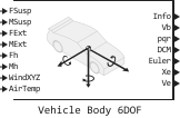
Description
Block Vehicle body 6DOF Implements a model of a rigid two-axle vehicle body (TC) with six degrees of freedom for calculating longitudinal, transverse, vertical motion, as well as pitch, roll, and yaw motion. The unit takes into account body weight, inertia, aerodynamic drag, road slope and weight distribution between the axles due to suspension and external forces and moments. Use the options on the tab Inertial Loads to analyze vehicle dynamics under various load conditions.
The unit can be connected to virtual sensors, a suspension system, or external systems such as body control drives. Use the block Vehicle body 6DOF in the study of smooth running and handling to simulate the effects of drag forces, passenger loads, and the location of suspension attachment points.
To use additional input ports, in the parameter group Input signals check the following boxes:
-
Hitch forces — opens the Fh port associated with the coupling force acting on the body in the vehicle’s frame of reference;
-
Hitch moments — opens the Mh port associated with the clutch moment in the vehicle’s reference frame.
Inertial loads
- To analyze vehicle dynamics under different load conditions, use the parameters in the tab Inertial Loads. In particular, you can set the following loads
-
-
Front transmission;
-
Front and back row passengers;
-
Cargo of the upper part of the body;
-
The cargo of the luggage section.
-
For each of the loads, you can specify the mass, position, and inertia.
The illustrations show the locations of the loads and the dimensions of the vehicle (TS). The table shows the corresponding settings for the position parameter sign.
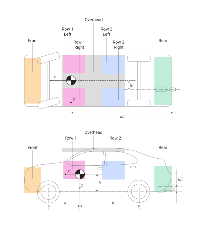
The illustration shows:
-
— the transverse distance from the center of mass (CM) to the coupling device along the axis in the reference frame of the vehicle;
-
— the longitudinal distance from the coupling device to the point of normal projection of the tractor’s center of gravity onto the common axis plane;
-
— the height of the coupling device above the plane of the axis along the axis in the reference frame of the vehicle;
-
— the height of the center of mass of the vehicle above the plane of the axis;
-
— the distance of the front and rear wheels, respectively, from the point of normal projection of the center of mass of the vehicle onto the common plane of the axis.
This table shows the parameter settings that determine the location of the loads indicated by the dots. To determine the position, the block uses the following distance vector:
-
The attachment point of the front suspension for loading along a fixed axis vehicle (vehicle);
-
TC centerline for loading along a fixed axis VEHICLE;
-
The attachment point of the front suspension for loading along a fixed axis The vehicle.
| Load | Parameter | Example of the location |
|---|---|---|
At the front |
Distance vector from front axle [z1R], m |
|
From above |
Distance vector from front axle [z2R], m |
|
Front row on the left |
Distance vector from front axle [z3R], m |
|
Front row on the right |
Distance vector from front axle [z4R], m |
|
Back row on the left |
Distance vector from front axle [z5R], m |
|
Back row on the right |
Distance vector from front axle [z6R], m |
|
From behind |
Distance vector from front axle [z7R], m |
|
Equations of motion
To determine the movement of a vehicle, the unit performs calculations of vehicle dynamics as a solid, air resistance, inertial loads, and coordinate transformations. The associated coordinate system of the body axes and the coordinate system of the vehicle are the same.
Block Vehicle body 6DOF It takes into account the rotation of the associated coordinate system around the inertial reference frame relative to the flat earth. The origin of the associated coordinate system is the center of gravity of the vehicle body.
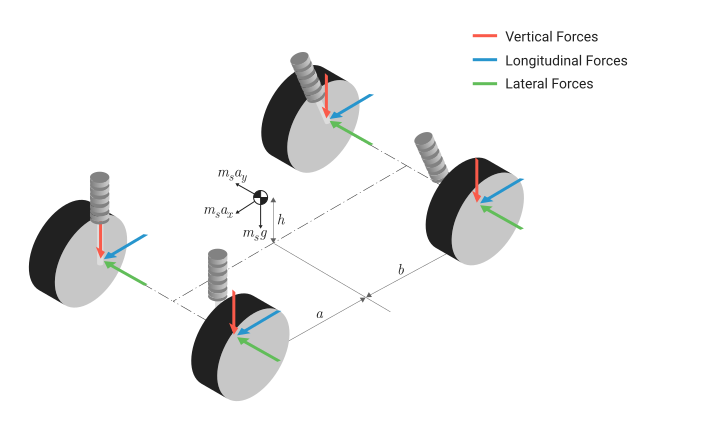
The illustration shows:
-
— the height of the center of mass of the vehicle above the plane of the axis;
-
— the distance of the front and rear wheels, respectively, from the point of normal projection of the center of mass of the vehicle on the common plane of the axis.
The block uses the following equation to calculate the translational motion of the associated coordinate system, where the applied forces are are in a related coordinate system, and the mass of the body is it is considered permanent:
where — moments of inertia of the vehicle body.
To determine the relationship between the angular velocity vector associated with the body, and the rate of change of the Euler angles , the block converts the Euler velocities into a related coordinate system:
Here
-
— the angle of rotation of the vehicle coordinate system around the axis , stationary relative to the ground (roll);
-
— the angle of rotation of the vehicle coordinate system around the axis , stationary relative to the ground (pitch);
-
— the angle of rotation of the vehicle coordinate system around the axis , stationary relative to the ground (yaw).
Reverse conversion gives the necessary relation to determine the Euler velocity vector:
The applied forces and moments are the sum of the forces of resistance, gravity, external forces, and suspension forces.:
where
-
— the resistance forces applied to the center of mass of the vehicle along the axes and in the reference frame of the vehicle body;
-
— the gravitational forces applied to the center of mass of the vehicle along the axes and in the reference frame of the vehicle body;
-
— external forces applied to the center of mass of the vehicle along the axes and in the reference frame of the vehicle body;
-
— suspension forces applied to the front left suspension attachment point along the axes and in the reference frame of the vehicle body;
-
— suspension forces applied to the front right suspension attachment point along the axes and in the reference frame of the vehicle body;
-
— suspension forces applied to the rear left suspension attachment point along the axes and in the reference frame of the vehicle body;
-
— suspension forces applied to the rear right suspension attachment point along the axes and in the reference frame of the vehicle body;
-
— suspension moments applied to the center of mass of the vehicle along the axes and in the reference frame of the vehicle body;
-
— the moments of the drag force applied to the center of mass of the vehicle along the axes and in the reference frame of the vehicle body;
-
— external moments applied to the center of mass of the vehicle along the axes and in the reference frame of the vehicle body.
Masses and moments of inertia of loads
The block uses the Huygens—Steiner theorem to calculate individual masses and moments of inertia of loads, taking into account the mass and moment of inertia of the vehicle:
Gravitational forces
The block uses a matrix of guiding cosines to transform the gravity vector in an inertially fixed frame of reference to a connected system.
powers and moments of resistance
To determine the relative velocity of the air flow, the unit subtracts the wind speed from the velocity of the vehicle’s center of mass. Using the relative velocity of the air flow, the unit determines the resistance forces :
where
-
— displacement of the center of mass, velocity and acceleration of the vehicle along the axis in the reference frame of the vehicle;
-
— displacement of the center of mass, velocity and acceleration of the vehicle along the axis in the reference frame of the vehicle;
-
— displacement of the center of mass, velocity and acceleration of the vehicle along the axis in the reference frame of the vehicle;
-
— wind speed along the axes and in the reference frame of the vehicle;
-
— ambient air temperature;
-
— specific gas constant of the atmosphere;
-
— coefficients of aerodynamic drag acting along the axes in the reference frame of TC , respectively;
-
— frontal surface area;
-
— absolute ambient pressure.
Using the relative velocity of the air flow, the unit determines the moments of resistance :
where
-
— the moment of air resistance during roll, pitch, yaw, respectively, relative to the axes in the reference frame of TC , respectively;
-
— the distance of the front and rear wheels, respectively, from the point of normal projection of the center of mass of the vehicle on the common plane of the axis.
External forces and moments_
External forces and the moments they are entered via ports FExt and MExt.
_ Strengths and moments of suspension_
The block assumes that the suspension forces and moments act on the following attachment points:
-
, — front left;
-
, — front right;
-
, — from the back on the left;
-
, — from the back to the right.
Ports
Entrance
Fsusp —
suspension forces acting on the vehicle
+
array
Details
The longitudinal, transverse and vertical suspension forces applied to the vehicle at the attachment point, measured in N. The signal dimension is 3×4:
| Array element | The axis | Wheel | The axis of power |
|---|---|---|---|
|
The front |
The left one |
The axis in the reference frame of the vehicle (longitudinal) |
|
The front |
The right one |
|
|
The back |
The left one |
|
|
The back |
The right one |
|
|
The front |
The left one |
The axis in the TC (transverse) frame of reference |
|
The front |
The right one |
|
|
The back |
The left one |
|
|
The back |
The right one |
|
|
The front |
The left one |
The axis in the TC reference frame (vertical) |
|
The front |
The right one |
|
|
The back |
The left one |
|
|
The back |
The right one |
| Типы данных |
|
| Support for complex numbers |
None |
# Msusp —
the moment of suspension on the vehicle
+
array
Details
The longitudinal, transverse and vertical suspension torques applied to the vehicle at the attachment point, measured in nm. The signal dimension is 3×4:
| Array element | The axis | Wheel | The axis of the moment |
|---|---|---|---|
|
The front |
The left one |
The axis in the reference frame of the vehicle (longitudinal) |
|
The front |
The right one |
|
|
The back |
The left one |
|
|
The back |
The right one |
|
|
The front |
The left one |
The axis in the TC (transverse) frame of reference |
|
The front |
The right one |
|
|
The back |
The left one |
|
|
The back |
The right one |
|
|
The front |
The left one |
The axis in the TC reference frame (vertical) |
|
The front |
The right one |
|
|
The back |
The left one |
|
|
The back |
The right one |
| Типы данных |
|
| Support for complex numbers |
None |
FExt —
external forces acting on the vehicle
+
vector
Details
External forces acting on the vehicle, measured in H, given as a vector of size 1×3 or 3×1:
or
| Array element | The axis of power |
|---|---|
|
The axis in the reference frame of the vehicle (longitudinal) |
|
The axis in the TC (transverse) frame of reference |
|
The axis in the TC reference frame (vertical) |
| Типы данных |
|
| Support for complex numbers |
None |
MExt —
external moments acting on the vehicle
+
vector
Details
External torques acting on the vehicle, measured in nm, given as a vector 1×3 or 3×1:
or
| Array element | The axis of the moment |
|---|---|
|
The axis in the reference frame of the vehicle (longitudinal) |
|
The axis in the TC (transverse) frame of reference |
|
The axis in the TC reference frame (vertical) |
| Типы данных |
|
| Support for complex numbers |
None |
Fh —
the tension force of the coupling device on the body
+
array
Details
The tension force of the coupling device applied to the body at the attachment point of the coupling device, , in the vehicle reference frame, measured in H, specified as an array of size 1×3 or 3×1.
Dependencies
To use this port, in the parameter group Input signals check the box Hitch forces.
| Типы данных |
|
| Support for complex numbers |
None |
Mh —
coupling moment relative to the body
+
array
Details
Coupling moment at the attachment point, , relative to the reference frame of the vehicle, measured in nm, specified as an array of size 1×3 or 3×1.
Dependencies
To use this port, in the parameter group Input signals check the box Hitch moments.
| Типы данных |
|
| Support for complex numbers |
None |
WindXYZ —
wind speed
+
scalar
Details
Wind speed, , along the inertial axes , measured in m/s, specified as an array of size 1×3 or 3×1.
| Типы данных |
|
| Support for complex numbers |
None |
AirTemp —
ambient temperature
+
scalar
Details
Ambient temperature , measured in K, given as a scalar.
Dependencies
To use this port, in the parameter group Environment check the box Air temperature.
| Типы данных |
|
| Support for complex numbers |
None |
Output
Info —
information signal
+
the tire
Details
A bus containing the results of the block calculation.
| Signal | Description | Value | Units of measurement | |||||
|---|---|---|---|---|---|---|---|---|
|
|
|
|
Displacement of the CM of the vehicle along an axis fixed relative to the earth |
Calculated |
m |
||
|
Displacement of the CM of the vehicle along an axis fixed relative to the earth |
Calculated |
m |
|||||
|
Displacement of the CM of the vehicle along an axis fixed relative to the earth |
Calculated |
m |
|||||
|
|
The velocity of the CM of the vehicle along an axis fixed relative to the earth |
Calculated |
m/s |
||||
|
The velocity of the CM of the vehicle along an axis fixed relative to the earth |
Calculated |
m/s |
|||||
|
The velocity of the CM of the vehicle along an axis fixed relative to the earth |
Calculated |
m/s |
|||||
|
|
The angle of rotation of the reference frame of the vehicle around an axis fixed relative to the earth (roll) |
Calculated |
glad |
||||
|
The angle of rotation of the reference frame of the vehicle around an axis fixed relative to the earth (pitch) |
Calculated |
rad |
|||||
|
The angle of rotation of the reference frame of the vehicle around an axis fixed relative to the earth (yaw) |
Calculated |
glad |
|||||
|
|
|
|
Displacement of the front left axis along the axis fixed relative to the ground |
Calculated |
m |
||
|
Displacement of the front left axis along the axis fixed relative to the ground |
Calculated |
m |
|||||
|
Displacement of the front left axis along the axis fixed relative to the ground |
Calculated |
m |
|||||
|
|
The speed of the front left axis along the axis fixed relative to the ground |
Calculated |
m/s |
||||
|
The speed of the front left axis along the axis fixed relative to the ground |
Calculated |
m/s |
|||||
|
The speed of the front left axis along the axis fixed relative to the ground |
Calculated |
m/s |
|||||
|
|
|
Displacement of the front right axis along the axis fixed relative to the ground |
Calculated |
m |
|||
|
Displacement of the front right axis along the axis fixed relative to the ground |
Calculated |
m |
|||||
|
Displacement of the front right axis along the axis fixed relative to the ground |
Calculated |
m |
|||||
|
|
The speed of the front right axis along the axis fixed relative to the ground |
Calculated |
m/s |
||||
|
The speed of the front right axis along the axis fixed relative to the ground |
Calculated |
m/s |
|||||
|
The speed of the front right axis along the axis fixed relative to the ground |
Calculated |
m/s |
|||||
|
|
|
|
Displacement of the rear left axis along the axis fixed relative to the ground |
Calculated |
m |
||
|
Displacement of the rear left axis along the axis fixed relative to the ground |
Calculated |
m |
|||||
|
Displacement of the rear left axis along the axis fixed relative to the ground |
Calculated |
m |
|||||
|
|
The speed of the rear left axis along the axis fixed relative to the ground |
Calculated |
m/s |
||||
|
The speed of the rear left axis along the axis fixed relative to the ground |
Calculated |
m/s |
|||||
|
The speed of the rear left axis along the axis fixed relative to the ground |
Calculated |
m/s |
|||||
|
|
|
Displacement of the rear right axis along the axis fixed relative to the ground |
Calculated |
m |
|||
|
Displacement of the rear right axis along the axis fixed relative to the ground |
Calculated |
m |
|||||
|
Displacement of the rear right axis along the axis fixed relative to the ground |
Calculated |
m |
|||||
|
|
The speed of the rear right axis along the axis fixed relative to the ground |
Calculated |
m/s |
||||
|
The speed of the rear right axis along the axis fixed relative to the ground |
Calculated |
m/s |
|||||
|
The speed of the rear right axis along the axis fixed relative to the ground |
Calculated |
m/s |
|||||
|
|
|
Displacement of the coupling device relative to the axis plane along the axis fixed relative to the ground |
Calculated |
m |
|||
|
Displacement of the coupling device relative to the axis plane along the axis fixed relative to the ground |
Calculated |
m |
|||||
|
Displacement of the coupling device relative to the axis plane along the axis fixed relative to the ground |
Calculated |
m |
|||||
|
|
The speed of the vehicle’s movement along an axis fixed relative to the earth |
Calculated |
m/s |
||||
|
The speed of the vehicle’s movement along an axis fixed relative to the earth |
Calculated |
m/s |
|||||
|
The speed of the vehicle’s movement along an axis fixed relative to the earth |
Calculated |
m/s |
|||||
|
|
|
Displacement of the vehicle chassis relative to the axis plane along the axis fixed relative to the ground |
Calculated |
m |
|||
|
Displacement of the vehicle chassis relative to the axis plane along the axis fixed relative to the ground |
Calculated |
m |
|||||
|
Displacement of the vehicle chassis relative to the axis plane along the axis fixed relative to the ground |
Calculated |
m |
|||||
|
|
The rate of displacement of the vehicle chassis along an axis fixed relative to the ground |
Calculated |
m/s |
||||
|
The rate of displacement of the vehicle chassis along an axis fixed relative to the ground |
Calculated |
m/s |
|||||
|
The rate of displacement of the vehicle chassis along an axis fixed relative to the ground |
Calculated |
m/s |
|||||
|
|
|
|
The velocity of the CM of the vehicle along an axis fixed relative to the vehicle |
Calculated |
m/s |
||
|
The velocity of the CM of the vehicle along an axis fixed relative to the vehicle |
Calculated |
m/s |
|||||
|
The velocity of the CM of the vehicle along an axis fixed relative to the vehicle |
Calculated |
m/s |
|||||
|
|
Angular velocity of the vehicle relative to the fixed axis (roll rate) |
Calculated |
rad/s |
||||
|
Angular velocity of the vehicle relative to the fixed axis (pitch velocity) |
Calculated |
rad/s |
|||||
|
Angular velocity of the vehicle relative to the fixed axis (yaw rate) |
Calculated |
rad/s |
|||||
|
|
Acceleration of the CM of the vehicle along an axis fixed relative to the vehicle |
Calculated |
gn |
||||
|
Acceleration of the CM of the vehicle along an axis fixed relative to the vehicle |
Calculated |
gn |
|||||
|
Acceleration of the CM of the vehicle along an axis fixed relative to the vehicle |
Calculated |
gn |
|||||
|
Acceleration of the CM of the vehicle along an axis fixed relative to the vehicle |
Calculated |
m/s2 |
|||||
|
Acceleration of the CM of the vehicle along an axis fixed relative to the vehicle |
Calculated |
m/s2 |
|||||
|
Acceleration of the CM of the vehicle along an axis fixed relative to the vehicle |
Calculated |
m/s2 |
|||||
|
Matrix of guiding cosines |
Calculated |
rad |
|||||
|
|
|
The resulting force acting on the CM of the vehicle along an axis stationary relative to the vehicle |
Calculated |
N |
|||
|
The resulting force acting on the CM of the vehicle along an axis stationary relative to the vehicle |
Calculated |
N |
|||||
|
The resulting force acting on the CM of the vehicle along an axis stationary relative to the vehicle |
Calculated |
N |
|||||
|
|
An external force acting on the CM of the vehicle along an axis stationary relative to the vehicle |
Input |
N |
||||
|
An external force acting on the CM of the vehicle along an axis stationary relative to the vehicle |
Input |
N |
|||||
|
An external force acting on the CM of the vehicle along an axis stationary relative to the vehicle |
Input |
N |
|||||
|
|
|
The longitudinal force on the front left axis along the axis fixed relative to the vehicle |
Calculated |
N |
|||
|
Lateral force on the front left axis along a fixed axis relative to the vehicle |
Calculated |
N |
|||||
|
The normal force on the front left axis along the axis stationary relative to the vehicle |
Calculated |
N |
|||||
|
|
The longitudinal force on the front right axis along the axis fixed relative to the vehicle |
Calculated |
N |
||||
|
Lateral force on the front right axis along a fixed axis relative to the vehicle |
Calculated |
N |
|||||
|
The normal force on the front right axis along the axis stationary relative to the vehicle |
Calculated |
N |
|||||
|
|
|
The longitudinal force on the rear left axis along the axis fixed relative to the vehicle |
Calculated |
N |
|||
|
Lateral force on the rear left axis along the axis fixed relative to the vehicle |
Calculated |
N |
|||||
|
The normal force on the rear left axis along the axis stationary relative to the vehicle |
Calculated |
N |
|||||
|
|
The longitudinal force on the rear right axis along the axis fixed relative to the vehicle |
Calculated |
N |
||||
|
Lateral force on the rear right axis along the axis fixed relative to the vehicle |
Calculated |
N |
|||||
|
The normal force on the rear right axis along the axis stationary relative to the vehicle |
Calculated |
N |
|||||
|
|
The force applied to the body at the attachment point of the coupling device along the axis fixed relative to the vehicle |
Calculated |
N |
||||
|
The force applied to the body at the attachment point of the coupling device along the axis fixed relative to the vehicle |
Calculated |
N |
|||||
|
The force applied to the body at the attachment point of the coupling device along the axis fixed relative to the vehicle |
Calculated |
N |
|||||
|
|
|
|
The force acting on the front left tire along a fixed axis relative to the vehicle |
Calculated |
N |
||
|
The force acting on the front left tire along a fixed axis relative to the vehicle |
Calculated |
N |
|||||
|
The force acting on the front left tire along a fixed axis relative to the vehicle |
Calculated |
N |
|||||
|
|
The force acting on the front right tire along the axis fixed relative to the vehicle |
Calculated |
N |
||||
|
The force acting on the front right tire along the axis fixed relative to the vehicle |
Calculated |
N |
|||||
|
The force acting on the front right tire along the axis fixed relative to the vehicle |
Calculated |
N |
|||||
|
|
|
The force acting on the rear left tire along a fixed axis relative to the vehicle |
Calculated |
N |
|||
|
The force acting on the rear left tire along a fixed axis relative to the vehicle |
Calculated |
N |
|||||
|
The force acting on the rear left tire along a fixed axis relative to the vehicle |
Calculated |
N |
|||||
|
|
The force acting on the rear right tire along a fixed axis relative to the vehicle |
Calculated |
N |
||||
|
The force acting on the rear right tire along a fixed axis relative to the vehicle |
Calculated |
N |
|||||
|
The force acting on the rear right tire along a fixed axis relative to the vehicle |
Calculated |
N |
|||||
|
|
The drag force acting on the vehicle’s CM along an axis that is stationary relative to the vehicle |
Calculated |
N |
||||
|
The drag force acting on the vehicle’s CM along an axis that is stationary relative to the vehicle |
Calculated |
N |
|||||
|
The drag force acting on the vehicle’s CM along an axis that is stationary relative to the vehicle |
Calculated |
N |
|||||
|
|
The force of gravity acting on the CM of the vehicle vehicle along the axis fixed relative to the vehicle |
Calculated |
N |
||||
|
The force of gravity acting on the CM of the vehicle vehicle along the axis fixed relative to the vehicle |
Calculated |
N |
|||||
|
The force of gravity acting on the CM of the vehicle vehicle along the axis fixed relative to the vehicle |
Calculated |
N |
|||||
|
|
|
The moment of inertia acting on the CM of the vehicle relative to the fixed axis |
Calculated |
N⋅m |
|||
|
The moment of inertia acting on the CM of the vehicle relative to the fixed axis |
Calculated |
N⋅m |
|||||
|
The moment of inertia acting on the CM of the vehicle relative to the fixed axis |
Calculated |
N⋅m |
|||||
|
|
The moment of resistance acting on the CM of the vehicle relative to the fixed axis |
Calculated |
N⋅m |
||||
|
The moment of resistance acting on the CM of the vehicle relative to the fixed axis |
Calculated |
N⋅m |
|||||
|
The moment of resistance acting on the CM of the vehicle relative to the fixed axis |
Calculated |
N⋅m |
|||||
|
|
The external moment acting on the CM of the vehicle relative to the fixed axis |
Calculated |
N⋅m |
||||
|
The external moment acting on the CM of the vehicle relative to the fixed axis |
Calculated |
N⋅m |
|||||
|
The external moment acting on the CM of the vehicle relative to the fixed axis |
Calculated |
N⋅m |
|||||
|
|
The moment of force that occurs at the attachment point of the coupling device relative to the fixed axis |
Calculated |
N⋅m |
||||
|
The moment of force that occurs at the attachment point of the coupling device relative to the fixed axis |
Calculated |
N⋅m |
|||||
|
The moment of force that occurs at the attachment point of the coupling device relative to the fixed axis |
Calculated |
N⋅m |
|||||
|
|
|
|
Displacement of the front left axis along the axis fixed relative to the vehicle |
Calculated |
m |
||
|
Displacement of the front left axis along the axis fixed relative to the vehicle |
Calculated |
m |
|||||
|
Displacement of the front left axis along the axis fixed relative to the vehicle |
Calculated |
m |
|||||
|
|
The speed of the front left axis along the fixed axis relative to the vehicle |
Calculated |
m/s |
||||
|
The speed of the front left axis along the fixed axis relative to the vehicle |
Calculated |
m/s |
|||||
|
The speed of the front left axis along the fixed axis relative to the vehicle |
Calculated |
m/s |
|||||
|
|
|
Displacement of the front right axis along the axis fixed relative to the vehicle |
Calculated |
m |
|||
|
Displacement of the front right axis along the axis fixed relative to the vehicle |
Calculated |
m |
|||||
|
Displacement of the front right axis along the axis fixed relative to the vehicle |
Calculated |
m |
|||||
|
|
The speed of the front right axle along the fixed axis relative to the vehicle |
Calculated |
m/s |
||||
|
The speed of the front right axle along the fixed axis relative to the vehicle |
Calculated |
m/s |
|||||
|
The speed of the front right axle along the fixed axis relative to the vehicle |
Calculated |
m/s |
|||||
|
|
|
|
Displacement of the rear left axis along the axis fixed relative to the vehicle |
Calculated |
m |
||
|
Displacement of the rear left axis along the axis fixed relative to the vehicle |
Calculated |
m |
|||||
|
Displacement of the rear left axis along the axis fixed relative to the vehicle |
Calculated |
m |
|||||
|
|
The speed of the rear left axis along the fixed axis relative to the vehicle |
Calculated |
m/s |
||||
|
The speed of the rear left axis along the fixed axis relative to the vehicle |
Calculated |
m/s |
|||||
|
The speed of the rear left axis along the fixed axis relative to the vehicle |
Calculated |
m/s |
|||||
|
|
|
Displacement of the rear right axis along the axis fixed relative to the vehicle |
Calculated |
m |
|||
|
Displacement of the rear right axis along the axis fixed relative to the vehicle |
Calculated |
m |
|||||
|
Displacement of the rear right axis along the axis fixed relative to the vehicle |
Calculated |
m |
|||||
|
|
The speed of the rear right axis along the fixed axis relative to the vehicle |
Calculated |
m/s |
||||
|
The speed of the rear right axis along the fixed axis relative to the vehicle |
Calculated |
m/s |
|||||
|
The speed of the rear right axis along the fixed axis relative to the vehicle |
Calculated |
m/s |
|||||
|
|
|
Displacement of the coupling device relative to the axis plane along the axis fixed relative to the vehicle |
Input |
m |
|||
|
Displacement of the coupling device relative to the axis plane along the axis fixed relative to the vehicle |
Input |
m |
|||||
|
Displacement of the coupling device relative to the axis plane along the axis fixed relative to the vehicle |
Input |
m |
|||||
|
|
The rate of displacement of the coupling device along the axis fixed relative to the vehicle |
Calculated |
m/s |
||||
|
The rate of displacement of the coupling device along the axis fixed relative to the vehicle |
Calculated |
m/s |
|||||
|
The rate of displacement of the coupling device along the axis fixed relative to the vehicle |
Calculated |
m/s |
|||||
|
|
Applied external power |
Calculated |
W |
||||
|
Power loss due to resistance |
Calculated |
W |
|||||
|
|
|
Displacement of the vehicle chassis relative to the axis plane along the fixed axis |
Input |
m |
|||
|
Displacement of the vehicle chassis relative to the axis plane along the fixed axis |
Input |
m |
|||||
|
Displacement of the vehicle chassis relative to the axis plane along the fixed axis |
Input |
m |
|||||
|
|
The rate of displacement of the vehicle chassis along a fixed axis relative to the vehicle |
Calculated |
m/s |
||||
|
The rate of displacement of the vehicle chassis along a fixed axis relative to the vehicle |
Calculated |
m/s |
|||||
|
The rate of displacement of the vehicle chassis along a fixed axis relative to the vehicle |
Calculated |
m/s |
|||||
|
|
Body sliding angle |
Calculated |
glad |
||||
| Типы данных |
|
| Support for complex numbers |
None |
Vb —
the speed of the vehicle along the reference frame associated with the vehicle
 +
`vector`
Details
The velocity of the vehicle’s center of mass along the axes and , stationary relative to the vehicle, measured in m/s, returned as a vector.
| Типы данных |
|
| Support for complex numbers |
None |
pqr —
the angular velocity of the vehicle relative to the reference frame associated with the vehicle
+
vector
Details
Angular velocity of the vehicle’s center of mass relative to the axes (roll speed), (pitch velocity) and (yaw velocity), stationary relative to the vehicle, measured in rad/s, returned as a vector.
| Типы данных |
|
| Support for complex numbers |
None |
DCM —
matrix of guiding cosines
+
array
Details
The matrix of guiding cosines in radians returned as an array.
| Типы данных |
|
| Support for complex numbers |
None |
Euler —
Euler angles
+
array
Details
Euler angles and , measured in rad, returned as an array.
| Типы данных |
|
| Support for complex numbers |
None |
Xe —
the position of the vehicle in the inertial reference frame
+
vector
Details
The position of the center of mass of the vehicle stationary relative to the inertial coordinate system of the axes and , measured in meters, returned as a vector.
| Типы данных |
|
| Support for complex numbers |
None |
Ve —
vehicle velocity in an inertial reference frame
+
vector
Details
The velocity of the vehicle’s center of mass along axes that are stationary relative to the inertial coordinate system and , measured in m/s, returned as a vector.
| Типы данных |
|
| Support for complex numbers |
None |
Parameters
Main tab
Input signals
# Hitch forces — activating the input port Fh
Details
Select this option to activate the input port Fh for coupling forces.
| Default value |
|
| Program usage name |
|
| Tunable |
No |
| Evaluatable |
Yes |
# Hitch moments — activation of the input port Mh
Details
Select this option to activate the Mh input port for coupling moments.
| Default value |
|
| Program usage name |
|
| Tunable |
No |
| Evaluatable |
Yes |
Chassis
# Vehicle mass m, kg — vehicle weight
Details
Vehicle weight , measured in kg .
| Default value |
|
| Program usage name |
|
| Tunable |
No |
| Evaluatable |
Yes |
# Longitudinal distance from center of mass to front axle a, m — distance
Details
Distance from the center of mass of the vehicle to the front axle, measured in meters.
| Default value |
|
| Program usage name |
|
| Tunable |
No |
| Evaluatable |
Yes |
# Longitudinal distance from center of mass to rear axle b, m — distance
Details
Distance from the center of mass of the vehicle to the front axle, measured in meters.
| Default value |
|
| Program usage name |
|
| Tunable |
No |
| Evaluatable |
Yes |
# Lateral distance from geometric centerline to center of mass d, m — distance
Details
Transverse distance from the geometric centerline to the center of mass, measured in meters, along an axis stationary relative to the vehicle . Positive values indicate that the vehicle’s center of mass is to the right of the geometric centerline. Negative values indicate that the center of mass of the vehicle is to the left of the geometric centerline.
| Default value |
|
| Program usage name |
|
| Tunable |
No |
| Evaluatable |
Yes |
# Vertical distance from center of mass to axle plane, h [m]: — distance
Details
Vertical distance from the center of mass of the vehicle to the plane of the axis, measured in meters.
| Default value |
|
| Program usage name |
|
| Tunable |
No |
| Evaluatable |
Yes |
# Longitudinal distance from center of mass to hitch dh, m — distance
Details
The longitudinal distance from the center of mass to the coupling device, measured in meters.
Dependencies
To use this parameter, in the parameter group Input signals check the box Hitch forces or Hitch moments.
| Default value |
|
| Program usage name |
|
| Tunable |
No |
| Evaluatable |
Yes |
# Lateral distance from geometric centerline to hitch hl, m — distance
Details
Transverse distance from the center of mass to the coupling device, measured in meters.
Dependencies
To use this parameter, in the parameter group Input signals check the box Hitch forces or Hitch moments.
| Default value |
|
| Program usage name |
|
| Tunable |
No |
| Evaluatable |
Yes |
# Vertical distance from hitch to axle plane hh, m — distance
Details
Vertical distance from the coupling device to the axis plane, measured in meters.
Dependencies
To use this parameter, in the parameter group Input signals check the box Hitch forces or Hitch moments.
| Default value |
|
| Program usage name |
|
| Tunable |
No |
| Evaluatable |
Yes |
# Initial position in inertial frame Xe_o = [Xeo, Yeo, Zeo], m — starting position
Details
Starting position vehicle in an inertial reference frame, measured in meters.
| Default value |
|
| Program usage name |
|
| Tunable |
No |
| Evaluatable |
Yes |
# Initial velocity in body axes xbdot_o = [xdot_o, ydot_0, xdot_o], m/s — initial velocity
Details
The initial velocity of the vehicle’s center of mass along the axes and , stationary relative to the vehicle, measured in m/s.
| Default value |
|
| Program usage name |
|
| Tunable |
No |
| Evaluatable |
Yes |
# Initial Euler orientation eul_o = [roll, pitch, yaw], rad — initial rotation
Details
The initial rotation of the Eulerian coordinate system associated with the vehicle around the axes (roll), (pitch) and (yaw) stationary relative to the Ground, measured in radians.
| Default value |
|
| Program usage name |
|
| Tunable |
No |
| Evaluatable |
Yes |
# Initial body rotation rates p_0 = [p, q, r], rad/s — initial rotation speed
Details
The initial angular velocity of the vehicle’s center of mass around the axes (roll speed), (pitch velocity) and (yaw velocity), stationary relative to the vehicle, measured in rad/s.
| Default value |
|
| Program usage name |
|
| Tunable |
No |
| Evaluatable |
Yes |
# Chassis inertia tensor [Iveh], kg*m^2 — vehicle inertia
Details
Vehicle inertia tensor by dimension 3×3. The elements of the tensor are measured in kg⋅m2.
| Default value |
|
| Program usage name |
|
| Tunable |
No |
| Evaluatable |
Yes |
# track widths w = [front, rear], m — track width
Details
The width of the front and rear tracks, measured in meters, set as a vector of size 1×2.
| Default value |
|
| Program usage name |
|
| Tunable |
No |
| Evaluatable |
Yes |
Aerodynamic
# Longitudinal drad area Af, m^2 — cross-sectional area of the vehicle
Details
Effective cross-sectional area of the vehicle to calculate the aerodynamic drag force acting on the vehicle, measured in m ^2 ^.
| Default value |
|
| Program usage name |
|
| Tunable |
No |
| Evaluatable |
Yes |
# Longitudinal drag coefficient Cd — aerodynamic drag
Details
Dimensionless coefficient of aerodynamic drag .
| Default value |
|
| Program usage name |
|
| Tunable |
No |
| Evaluatable |
Yes |
# Longitudinal lift coefficient CI — lifting force
Details
Dimensionless coefficient of pneumatic lifting force .
| Default value |
|
| Program usage name |
|
| Tunable |
No |
| Evaluatable |
Yes |
# Longitudinal drag pitch moment Cpm — pitch resistance
Details
The dimensionless coefficient of the moment of longitudinal pitch resistance .
| Default value |
|
| Program usage name |
|
| Tunable |
No |
| Evaluatable |
Yes |
# Relative wind angle vector [beta_w], rad — wind angle
Details
Vector of relative wind angle , measured in radians.
| Default value |
|
| Program usage name |
|
| Tunable |
No |
| Evaluatable |
Yes |
# Side force coefficient vector [Cs] — lateral resistance force
Details
Vector of the dimensionless coefficient of lateral resistance .
| Default value |
|
| Program usage name |
|
| Tunable |
No |
| Evaluatable |
Yes |
# Yaw moment coefficient vector [Cym] — the moment of yaw resistance
Details
Vector of the dimensionless coefficient of the yaw moment .
| Default value |
|
| Program usage name |
|
| Tunable |
No |
| Evaluatable |
Yes |
Environment
# Absolute Pressure Pabs, Pa — atmospheric pressure
Details
Absolute atmospheric pressure in the environment , measured in Pa.
| Default value |
|
| Program usage name |
|
| Tunable |
No |
| Evaluatable |
Yes |
# Air temperature — an option for setting the air temperature
Details
Select this option to activate the AirTemp input port. Uncheck the box to set the air temperature using the parameter Air temperature Tair, K.
| Default value |
|
| Program usage name |
|
| Tunable |
No |
| Evaluatable |
Yes |
# Air temperature Tair, K — ambient temperature
Details
Ambient temperature , measured in K.
Dependencies
To use this option, uncheck the box. Air temperature.
| Default value |
|
| Program usage name |
|
| Tunable |
No |
| Evaluatable |
Yes |
# Gravitational acceleration g, m/s^2 — gravity
Details
Acceleration of free fall measured in m/s 2.
| Default value |
|
| Program usage name |
|
| Tunable |
No |
| Evaluatable |
Yes |
Simulation
# Longitudinal velocity tolerance xdot_tol, m/s — allowance
Details
Longitudinal speed tolerance , measured in m/s .
The unit uses this parameter to avoid division by zero when calculating the sliding angle of the body. .
| Default value |
|
| Program usage name |
|
| Tunable |
No |
| Evaluatable |
Yes |
# Geometric longitudinal offset from axle pane longOff, m — longitudinal displacement
Details
Displacement of the vehicle chassis relative to the axis plane along the axis , stationary relative to the body, measured in meters. When using the 3D visualization mechanism, it is recommended to use this offset to position the chassis regardless of the vehicle’s center of gravity.
| Default value |
|
| Program usage name |
|
| Tunable |
No |
| Evaluatable |
Yes |
# Geometric lateral offset from axle plane latOff, m — lateral displacement
Details
Displacement of the vehicle chassis from the central plane along the axis , stationary relative to the body, measured in meters. When using the 3D visualization mechanism, it is recommended to use this offset to position the chassis regardless of the vehicle’s center of gravity.
| Default value |
|
| Program usage name |
|
| Tunable |
No |
| Evaluatable |
Yes |
# Geometric vertical offset from axle plane vertOff, m — vertical displacement
Details
Displacement of the vehicle chassis relative to the axis plane along the axis , stationary relative to the body, measured in meters. When using the 3D visualization mechanism, it is recommended to use this offset to position the chassis regardless of the vehicle’s center of gravity.
| Default value |
|
| Program usage name |
|
| Tunable |
No |
| Evaluatable |
Yes |
# Wrap Euler angles, wrapAng — the ability to limit Euler angles
Details
The ability to limit the Euler angles to an interval [−π, π]. For vehicle maneuvers that may involve yaw axis turns beyond this range, it is recommended to uncheck this box if you want to:
-
Track the full rotation angle of the vehicle along the yaw axis.
-
Avoid gaps in vehicle condition assessments.
| Default value |
|
| Program usage name |
|
| Tunable |
No |
| Evaluatable |
Yes |
Inertial Loads
Front
# Mass z1m, kg — weight
Details
Weight z1m, measured in kg .
| Default value |
|
| Program usage name |
|
| Tunable |
No |
| Evaluatable |
Yes |
# Distance vector from front axle [z1R], m — distance
Details
Distance vector z1R from the front axle to the load, measured in meters. The dimension of the vector is 1×3.
| Array element | Description |
|---|---|
|
The attachment point of the front suspension to the load, along the axis , stationary relative to the vehicle |
|
The centerline of the vehicle to the load, along the axis , stationary relative to the vehicle |
|
The attachment point of the front suspension to the load, along the axis , stationary relative to the vehicle |
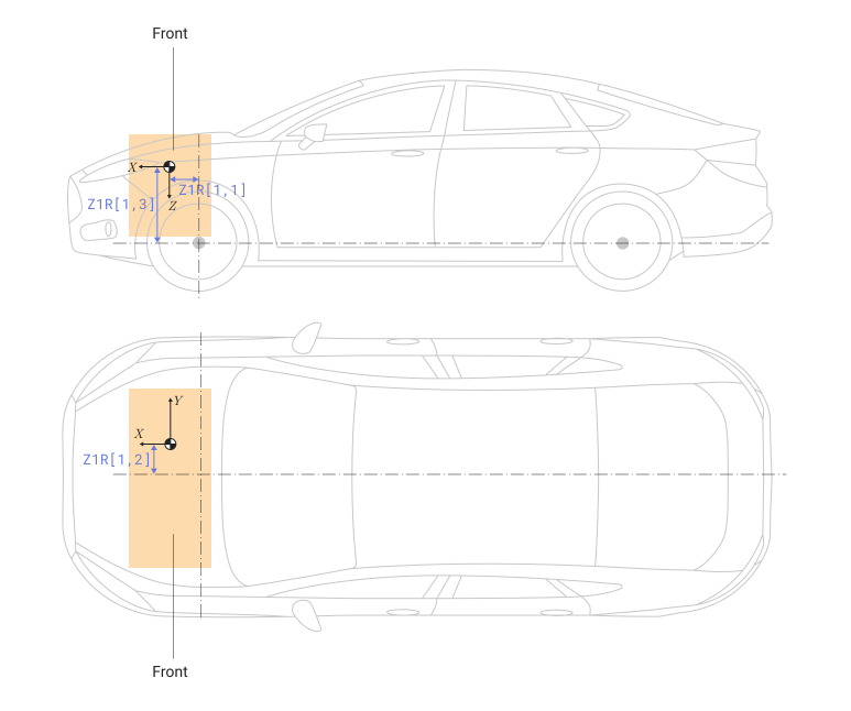
For example, the following table provides a summary of the parameters that determine the location of the load, indicated by dots.
| Example of the location | Sign |
|---|---|
Ahead of the front axle |
|
To the right of the centerline of the vehicle |
|
Above the mounting point of the front axle suspension |
|
| Default value |
|
| Program usage name |
|
| Tunable |
No |
| Evaluatable |
Yes |
# Inertia tensor [z1I], kg*m^2 — inertia
Details
The inertia tensor z1I by dimension 3×3. The elements of the tensor are measured in kg⋅m2.
The tensor uses a coordinate system with the origin at the center of mass of the load:
-
The axis — along an axis fixed relative to the vehicle ;
-
The axis — along an axis fixed relative to the vehicle ;
-
The axis — along an axis fixed relative to the vehicle .
| Default value |
|
| Program usage name |
|
| Tunable |
No |
| Evaluatable |
Yes |
Overhead
# Mass z2m, kg — weight
Details
Weight z2m, measured in kg .
| Default value |
|
| Program usage name |
|
| Tunable |
No |
| Evaluatable |
Yes |
# Distance vector from front axle [z2R], m — distance
Details
Distance vector z2R from the front axle to the load, measured in meters. The dimension of the vector is 1×3.
| Array element | Description |
|---|---|
|
The attachment point of the front suspension to the load, along the axis , stationary relative to the vehicle |
|
The centerline of the vehicle to the load, along the axis , stationary relative to the vehicle |
|
The attachment point of the front suspension to the load, along the axis , stationary relative to the vehicle |
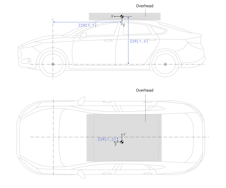
For example, the following table provides a summary of the parameters that determine the location of the load, indicated by dots.
| Example of the location | Sign |
|---|---|
Behind the front axle |
|
To the left of the centerline of the vehicle |
|
Above the mounting point of the front axle suspension |
|
| Default value |
|
| Program usage name |
|
| Tunable |
No |
| Evaluatable |
Yes |
# Inertia tensor [z2I], kg*m^2 — inertia
Details
The inertia tensor z2I by dimension 3×3. The elements of the tensor are measured in kg⋅m2.
The tensor uses a coordinate system with the origin at the center of mass of the load:
-
The axis — along an axis fixed relative to the vehicle ;
-
The axis — along an axis fixed relative to the vehicle ;
-
The axis — along an axis fixed relative to the vehicle .
| Default value |
|
| Program usage name |
|
| Tunable |
No |
| Evaluatable |
Yes |
Row 1, left side
# Mass, z3m [kg]: — weight
Details
Weight z3m, measured in kg .
| Default value |
|
| Program usage name |
|
| Tunable |
No |
| Evaluatable |
Yes |
# Distance vector from front axle [z3R], m — distance
Details
Distance vector z3R from the front axle to the load, measured in meters. The dimension of the vector is 1×3.
| Array element | Description |
|---|---|
|
The attachment point of the front suspension to the load, along the axis , stationary relative to the vehicle |
|
The centerline of the vehicle to the load, along the axis , stationary relative to the vehicle |
|
The attachment point of the front suspension to the load, along the axis , stationary relative to the vehicle |
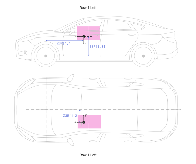
For example, the following table provides a summary of the parameters that determine the location of the load, indicated by dots.
| Example of the location | Sign |
|---|---|
Behind the front axle |
|
To the left of the centerline of the vehicle |
|
Above the mounting point of the front axle suspension |
|
| Default value |
|
| Program usage name |
|
| Tunable |
No |
| Evaluatable |
Yes |
# Inertia tensor [z3I], kg*m^2 — inertia
Details
The inertia tensor z3I by dimension 3×3. The elements of the tensor are measured in kg⋅m2.
The tensor uses a coordinate system with the origin at the center of mass of the load:
-
The axis — along an axis fixed relative to the vehicle ;
-
The axis — along an axis fixed relative to the vehicle ;
-
The axis — along an axis fixed relative to the vehicle .
| Default value |
|
| Program usage name |
|
| Tunable |
No |
| Evaluatable |
Yes |
Row 1, right side
# Mass z4m, kg — weight
Details
Weight z4m, measured in kg .
| Default value |
|
| Program usage name |
|
| Tunable |
No |
| Evaluatable |
Yes |
# Distance vector from front axle [z4R], m — distance
Details
Distance vector z4R from the front axle to the load, measured in meters. The dimension of the vector is 1×3.
| Array element | Description |
|---|---|
|
The attachment point of the front suspension to the load, along the axis , stationary relative to the vehicle |
|
The centerline of the vehicle to the load, along the axis , stationary relative to the vehicle |
|
The attachment point of the front suspension to the load, along the axis , stationary relative to the vehicle |
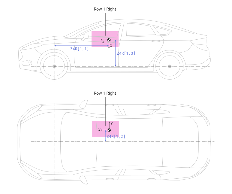
For example, the following table provides a summary of the parameters that determine the location of the load, indicated by dots.
| Example of the location | Sign |
|---|---|
Behind the front axle |
|
To the right of the centerline of the vehicle |
|
Above the mounting point of the front axle suspension |
|
| Default value |
|
| Program usage name |
|
| Tunable |
No |
| Evaluatable |
Yes |
# Inertia tensor [z4I], kg*m^2 — inertia
Details
The inertia tensor z4I by dimension 3×3. The elements of the tensor are measured in kg⋅m2.
The tensor uses a coordinate system with the origin at the center of mass of the load:
-
The axis — along an axis fixed relative to the vehicle ;
-
The axis — along an axis fixed relative to the vehicle ;
-
The axis — along an axis fixed relative to the vehicle .
| Default value |
|
| Program usage name |
|
| Tunable |
No |
| Evaluatable |
Yes |
Row 2, left side
# Mass z5m, kg — weight
Details
Weight z5m, measured in kg .
| Default value |
|
| Program usage name |
|
| Tunable |
No |
| Evaluatable |
Yes |
# Distance vector from front axle [z5R], m — distance
Details
Distance vector z5R from the front axle to the load, measured in meters. The dimension of the vector is 1×3.
| Array element | Description |
|---|---|
|
The attachment point of the front suspension to the load, along the axis , stationary relative to the vehicle |
|
The centerline of the vehicle to the load, along the axis , stationary relative to the vehicle |
|
The attachment point of the front suspension to the load, along the axis , stationary relative to the vehicle |
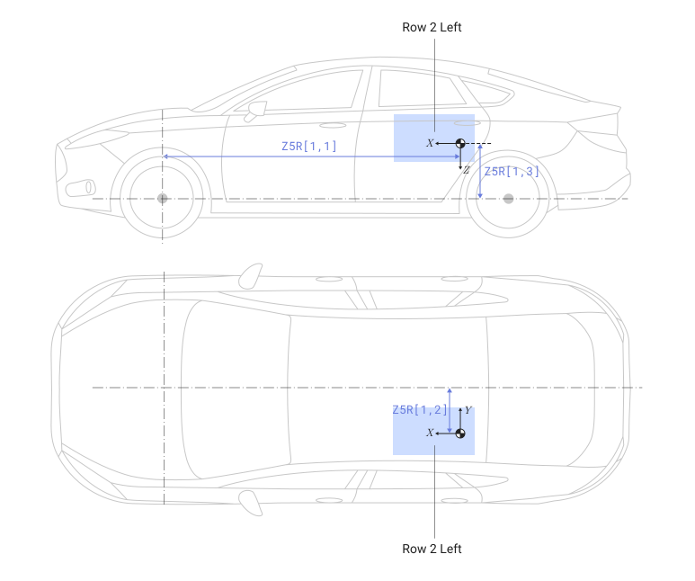
For example, the following table provides a summary of the parameters that determine the location of the load, indicated by dots.
| Example of the location | Sign |
|---|---|
Behind the front axle |
|
To the left of the centerline of the vehicle |
|
Above the mounting point of the front axle suspension |
|
| Default value |
|
| Program usage name |
|
| Tunable |
No |
| Evaluatable |
Yes |
# Inertia tensor [z5I], kg*m^2 — inertia
Details
The inertia tensor z5I by dimension 3×3. The elements of the tensor are measured in kg⋅m2.
The tensor uses a coordinate system with the origin at the center of mass of the load:
-
The axis — along an axis fixed relative to the vehicle ;
-
The axis — along an axis fixed relative to the vehicle ;
-
The axis — along an axis fixed relative to the vehicle .
| Default value |
|
| Program usage name |
|
| Tunable |
No |
| Evaluatable |
Yes |
Row 2, right side
# Mass z6m, kg — weight
Details
Weight z6m, measured in kg .
| Default value |
|
| Program usage name |
|
| Tunable |
No |
| Evaluatable |
Yes |
# Distance vector from front axle [z6R], m — distance
Details
Distance vector z6R from the front axle to the load, measured in meters. The dimension of the vector is 1×3.
| Array element | Description |
|---|---|
|
The attachment point of the front suspension to the load, along the axis , stationary relative to the vehicle |
|
The centerline of the vehicle to the load, along the axis , stationary relative to the vehicle |
|
The attachment point of the front suspension to the load, along the axis , stationary relative to the vehicle |
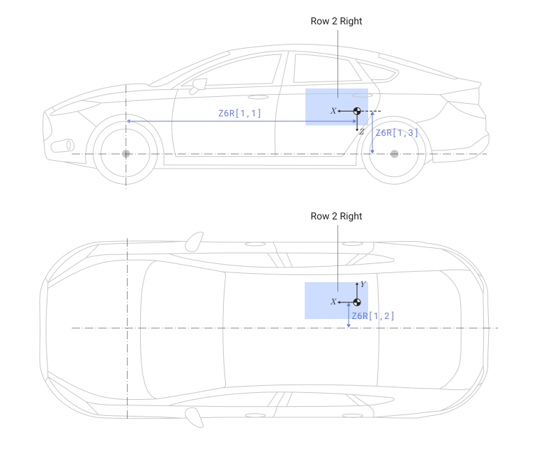
For example, the following table provides a summary of the parameters that determine the location of the load, indicated by dots.
| Example of the location | Sign |
|---|---|
Behind the front axle |
|
To the right of the centerline of the vehicle |
|
Above the mounting point of the front axle suspension |
|
| Default value |
|
| Program usage name |
|
| Tunable |
No |
| Evaluatable |
Yes |
# Inertia tensor [z6I], kg*m^2 — inertia
Details
The inertia tensor z6I by dimension 3×3. The elements of the tensor are measured in kg⋅m2.
The tensor uses a coordinate system with the origin at the center of mass of the load:
-
The axis — along an axis fixed relative to the vehicle ;
-
The axis — along an axis fixed relative to the vehicle ;
-
The axis — along an axis fixed relative to the vehicle .
| Default value |
|
| Program usage name |
|
| Tunable |
No |
| Evaluatable |
Yes |
Rear
# Mass z7m, kg — weight
Details
Weight z7m, measured in kg .
| Default value |
|
| Program usage name |
|
| Tunable |
No |
| Evaluatable |
Yes |
# Distance vector from front axle [z7R], m — distance
Details
Distance vector z7R from the front axle to the load, measured in meters. The dimension of the vector is 1×3.
| Array element | Description |
|---|---|
|
The attachment point of the front suspension to the load, along the axis , stationary relative to the vehicle |
|
The centerline of the vehicle to the load, along the axis , stationary relative to the vehicle |
|
The attachment point of the front suspension to the load, along the axis , stationary relative to the vehicle |
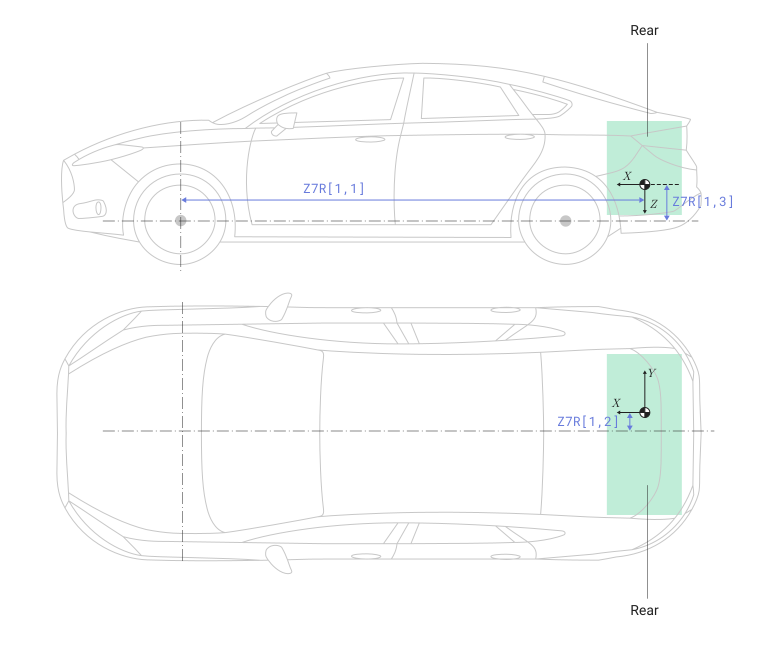
For example, the following table provides a summary of the parameters that determine the location of the load, indicated by dots.
| Example of the location | Sign |
|---|---|
Behind the front axle |
|
To the right of the centerline of the vehicle |
|
Above the mounting point of the front axle suspension |
|
| Default value |
|
| Program usage name |
|
| Tunable |
No |
| Evaluatable |
Yes |
# Inertia tensor [z7I], kg*m^2 — inertia
Details
The inertia tensor z7I by dimension 3×3. The elements of the tensor are measured in kg⋅m2.
The tensor uses a coordinate system with the origin at the center of mass of the load:
-
The axis — along an axis fixed relative to the vehicle ;
-
The axis — along an axis fixed relative to the vehicle ;
-
The axis — along an axis fixed relative to the vehicle .
| Default value |
|
| Program usage name |
|
| Tunable |
No |
| Evaluatable |
Yes |