M-PSK Modulator Baseband
Modulates data using the M-PSK method.
blockType: MPSKModulatorBaseband
|
Path in the library: |

Description
The M-PSK Modulator Baseband modulates the input signal using M-point phase manipulation (M-PSK) and returns a complex base signal at the output. Modulation order, , which is equivalent to the number of points in the signal constellation, is determined by the parameter M-ary number. The block accepts scalars or vector columns as input.
Ports
Input
#
In
—
Input signal
scalar | vector
Details
An input signal specified as an integer scalar, integer vector, or binary vector.
-
If the Input type parameter is set to
Integer, specify the elements of the input signal as integers from before . -
If the Input type parameter is set to
Bitspecify the input signal as a binary vector in which the number of elements is an integer multiple of the number of bits per character. The number of bits per character is .
| Data types |
|
| Complex numbers support |
I don’t |
Output
#
Out
—
M-PSK-modulated output signal
the complex scalar | complex vector
Details
The output signal returned as a complex scalar or vector. The output signal is a complex basic representation of the PSK-modulated signal.
| Data types |
|
| Complex numbers support |
Yes |
Parameters
Parameters
#
M-ary number —
the modulation order of the PSK signal constellation
Real number
Details
The modulation order is set as a positive integer, which is a power of two.
| Example |
|
| Default value |
|
| Program usage name |
|
| Tunable |
No |
| Evaluatable |
Yes |
#
Input type —
type of input signal
Bit | Integer
Details
Input signal elements specified as integers or bits.
If the Input type parameter is set to Bit, the number of samples in a frame must be an integer multiple of the number of bits per character. The number of bits per character is .
| Values |
|
| Default value |
|
| Program usage name |
|
| Tunable |
No |
| Evaluatable |
No |
#
Constellation ordering —
displaying characters
Binary | Gray | User-defined
Details
Symbolic representation of whole or groups bit inputs specified as Gray, Binary or User-defined.
-
Gray– The input signal is mapped to the output symbols using a Gray-coded signal constellation. -
Binary– the modulated symbol will be , where – phase shift in radians, – an integer input such that , and – the order of modulation. -
User-defined– size vector , which has unique integer values in the range, . The first element of this vector corresponds to the point of the signal constellation, which has the value , and subsequent elements go counterclockwise.
| Example |
|
| Values |
|
| Default value |
|
| Program usage name |
|
| Tunable |
No |
| Evaluatable |
No |
#
Constellation mapping —
displaying custom characters
Array of real numbers
Details
User-defined character display, set as -an element vector having unique integer values in the range ]. Use this parameter to set a custom order in which input integers are mapped to output integers.
The first element of this vector corresponds to the point of the signal constellation at an angle , and subsequent elements go counterclockwise. The last element corresponds to the point of the signal constellation . is the magnitude of the phase shift (parameter Phase offset (rad)), and – the modulation order (parameter M-ary number).
Dependencies
To use this parameter, set the Constellation ordering parameter to User-defined.
| Default value |
|
| Program usage name |
|
| Tunable |
No |
| Evaluatable |
Yes |
#
Phase offset (rad) —
phase shift
Real number
Details
The phase offset of the initial signal constellation in radians in the form of a real scalar.
| Example |
|
| Default value |
|
| Program usage name |
|
| Tunable |
No |
| Evaluatable |
Yes |
Data Type
#
Output data type —
type of output data
Float64 | Float32 | Float16 | Fixed-point
Details
The data type of the modulated output signal. Set as:
-
Float64 -
Float32 -
Float16 -
Fixed-point
| Values |
|
| Default value |
|
| Program usage name |
|
| Tunable |
No |
| Evaluatable |
No |
#
Output fixed-point type —
a vector of fixed-point values
Data type
Details
A vector of values of the output signal with a fixed point.
Dependencies
To use this parameter, set the Output data type parameter to Fixed-point.
| Default value |
|
| Program usage name |
|
| Tunable |
No |
| Evaluatable |
Yes |
Algorithms
For higher-order PSK signal constellations, the complex baseband form for the M-PSK signal usage of a binary-ordered symbol mapping looks like:
When the input is set to bits, groups of bits represent complex symbols for customized symbol mapping. The mapping can be binary, Gray-coded, or custom.
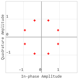
The advantage of Gray coding is that only one bit changes between adjacent points of the signal constellation, which leads to an improvement in the error rate.
This 8-PSK signal constellation uses Gray character encoding.