Rectangular QAM Demodulator Baseband
Data demodulation with rectangular QAM modulation.
blockType: RectangularQAMDemodulator
|
Path in the library: |

Description
Block Rectangular QAM Demodulator Baseband demodulates a signal modulated using quadrature amplitude modulation with a given order with a constellation on a rectangular grid.
All power values assume a nominal impedance 1 Om.
|
Ports
Output
#
OUT_1
—
demodulated signal
scalar | vector
Details
A demodulated signal returned as a scalar or vector.
The dimensions of the demodulated signal depend on the parameter values Output type and Decision type.
| Data types |
|
| Complex numbers support |
I don’t |
Input
#
IN_1
—
Input signal
scalar | vector
Details
An input signal specified as a scalar or column vector.
| Data types |
|
| Complex numbers support |
I don’t |
#
In
—
QAM-modulated signal
scalar | vector
Details
QAM is a modulated signal specified as a scalar or column vector.
Dependencies
To use this port, set the parameter Noise variance source value Port.
| Data types |
|
| Complex numbers support |
Yes |
#
Var
—
noise dispersion
scalar | vector
Details
The noise variance, given as a positive scalar or a vector of positive values. If noise dispersion or signal strength leads to calculations involving extreme positive or negative values, see the Hard QAM signal demodulation section for a review of the type of demodulation solution.
Dependencies
To use this port, set the parameter Noise variance source value Port.
| Data types |
|
| Complex numbers support |
I don’t |
Parameters
Main
#
M-ary number —
the order of modulation
Integer
Details
The modulation order is set as a positive integer equal to two. The order of modulation determines the number of points in the signal constellation.
it should have the form for some positive integer .
The block scales the signal constellation depending on the parameter value. Normalization method.
| Default value |
|
| Program usage name |
|
| Tunable |
No |
| Evaluatable |
Yes |
#
Output type —
type of output data
Integer | Bit
Details
Determines whether the block will output integers or binary representations of integers.
-
If set for the parameter Output type meaning
Integer, the block outputs integers in the range for each character. — this is the modulation order (M-ary number). -
If set for the parameter Output type meaning
Bit, and for the parameter Decision type — valueHard desicion, then for each character , the block outputs a group of a bit called a binary word, . -
If set for the parameter Output type meaning
Bit, and for the parameter Decision type — valueLog-likelihood ratioorApproximate log-likelihood ratio, the block outputs a bitwise LLR (communication loss signal) or an approximate LLR, respectively.
| Values |
|
| Default value |
|
| Program usage name |
|
| Tunable |
No |
| Evaluatable |
No |
#
Decision type —
type of solution
Hard desicion | Log-likelihood ratio | Approximate log-likelihood ratio
Details
The type of demodulation solution specified as Hard desicion, Log-likelihood ratio or Approximate log-likelihood ratio.
Dependencies
To use this parameter, set for the parameter Output type meaning Bit.
| Values |
|
| Default value |
|
| Program usage name |
|
| Tunable |
No |
| Evaluatable |
No |
#
Noise variance source —
the source of the noise dispersion
Port | Dialog
Details
The source of the noise dispersion, defined as Dialog or Port.
-
When selecting a value
Dialogto set the noise dispersion, use the parameter Noise variance. -
When selecting a value
PortThe Var port must be used to set the noise dispersion.
Dependencies
To use this parameter, set for the parameter Decision type meaning Approximate log-likelihood ratio or Log-likelihood ratio.
| Values |
|
| Default value |
|
| Program usage name |
|
| Tunable |
No |
| Evaluatable |
No |
#
Noise variance —
noise dispersion
Real number
Details
The noise variance, specified as a positive scalar or vector of positive values.
When setting a parameter Noise variance in the form of a scalar, this value is used for all elements of the input signal.
When setting a parameter Noise variance as a vector, the length of the vector should be equal to the number of columns in the input signal. Each element of the noise dispersion vector is applied to the corresponding column of the input signal.
This parameter is configured in normal mode, accelerator mode, and fast accelerator mode.
The exact LLR algorithm calculates exponentials using finite precision arithmetic. For calculations with very large positive or negative values, the exact LLR algorithm gives:
-
Infor−Infif the noise dispersion is very large; -
NaNif the noise dispersion and signal strength are very small.
The approximate LLR algorithm does not calculate exponents. You can avoid the results. Inf, -Inf and NaN using an approximate LLR algorithm.
Dependencies
To use this parameter, set for the parameter Decision type meaning Log-likelihood ratio or Approximate log-likelihood ratio, and for the parameter Noise variance source meaning Dialog.
| Default value |
|
| Program usage name |
|
| Tunable |
No |
| Evaluatable |
Yes |
#
Constellation ordering —
the order in which characters are displayed
Gray | Binary
Details
The order in which characters are displayed is set as Binary or Gray.
Parameter Constellation ordering defines how the block maps each character to a group of output bits or an integer.
| Values |
|
| Default value |
|
| Program usage name |
|
| Tunable |
No |
| Evaluatable |
No |
#
Normalization method —
the scaling method for the constellation
Min. distance between symbols | Average power | Peak power
Details
The constellation scaling method, defined as the minimum distance between symbols, average power, or peak power.
| Values |
|
| Default value |
|
| Program usage name |
|
| Tunable |
No |
| Evaluatable |
No |
#
Minimum distance —
the distance between the two closest points of the constellation
Real number
Details
The distance between the two closest points of the constellation, given as a positive scalar.
Dependencies
To use this parameter, set for the parameter Normalization method meaning Min. distance between symbols.
| Default value |
|
| Program usage name |
|
| Tunable |
No |
| Evaluatable |
Yes |
#
Average power, referenced to 1 ohm (watts) —
average power
Real number
Details
The average power of the symbols in the constellation in watts, given as a positive scalar. The power values assume a nominal impedance 1 Om.
The unit of measurement is Watts.
Dependencies
To use this parameter, set for the parameter Normalization method meaning Average power.
| Default value |
|
| Program usage name |
|
| Tunable |
No |
| Evaluatable |
Yes |
#
Peak power, referenced to 1 ohm (watts) —
peak power
Real number
Details
The maximum power of symbols in a constellation, given as a positive scalar. The power values assume a nominal impedance 1 Om.
The unit of measurement is Watts.
Dependencies
To use this parameter, set for the parameter Normalization method meaning Peak power.
| Default value |
|
| Program usage name |
|
| Tunable |
No |
| Evaluatable |
Yes |
#
Phase offset (rad) —
rotation of the signal constellation
Real number
Details
The rotation of the signal constellation, specified as a numeric scalar.
The unit of measurement is rad.
| Default value |
|
| Program usage name |
|
| Tunable |
No |
| Evaluatable |
Yes |
Algorithms
Hard QAM signal demodulation
Details
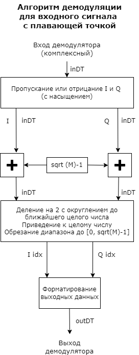
The demodulator algorithm converts the received values of the input signal constellations into -dimensional integer indexes of the characters I and Q in the range , and then converts these demodulated character indexes into formatted output values. — this is the parameter value M-ary number.
The calculation of the integer symbolic index is performed by derotation and scaling of the complex constellation of the input signal (possibly with noise) by the derotation coefficient and the denormalization coefficient, respectively. These coefficients are determined based on the phase shift (rad), the normalization method, and the corresponding parameters. These derated and denormalized values are added to to put them in an approximate range . — this is the added value of noise.
The resulting values are then scaled by dividing by two (or, equivalently, shifting right by one bit for fixed-point operations) to get a range of approximately for I and Q.
Noisy index values are rounded to the nearest integer and trimmed using saturation, and then converted to integer values of characters in the range. .
Finally, based on other block parameters, the integer index is mapped to a character value, which is formatted and converted to the selected output type.
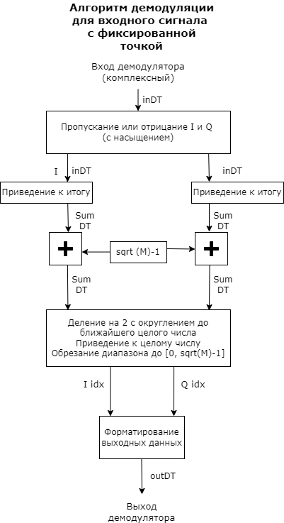
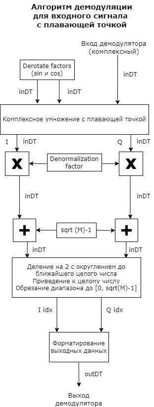
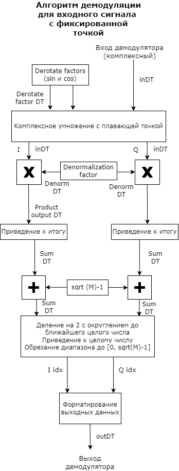
These figures show flowcharts for the operation of floating-point and fixed-point algorithms.
Floating point diagrams are used when the input data type is double or single.
Fixed-point diagrams are used when the input signal is a signed fixed-point data type. The diagram is simplified if the phase shift (rad) is a multiple of or the derived denormalization coefficient is 1.
|
|
|
|
Software demodulation of the QAM signal
Details
Two log likelihood ratio (LLR) algorithms with smooth decision making are available for software demodulation: exact LLR and approximate LLR.
The exact LLR algorithm is more accurate, but the execution speed is lower than that of the approximate LLR algorithm.
|
The exact LLR algorithm calculates exponentials using finite precision arithmetic. For calculations involving very large positive or negative values, the exact LLR algorithm gives the result:
The approximate LLR algorithm does not calculate exponents. You can avoid the results. |
Constellation size and scaling
Details
The set of signals contains points where — parameter value M-ary number.
it should have the form for some positive integer .
The block scales the signal constellation depending on what value is set for the parameter. Normalization method.
The following table lists the possible scaling conditions.
| Parameter value Normalization method | Zoom condition |
|---|---|
|
The nearest pair of points in the constellation is separated depending on the value of the parameter Minimum distance. |
|
The average power of the symbols in a constellation is a parameter Average power, referenced to 1 ohm (watts). |
|
The maximum power of symbols in a constellation is a parameter Peak power, referenced to 1 ohm (watts). |