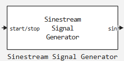
Sinestream Signal Generator
A sinusoidal waveform generator for evaluating the frequency response of a system.
blockType: SubSystem
|
Path in the library: |
Description
Block Sinestream Signal Generator It is used to generate sinusoidal disturbance input signals. This unit allows you to generate both scalar and vector signals, including three-phase sine, cosine, or both signals. Three-phase signals are useful in determining the frequency response of three-phase AC systems. For example, the generated signal can be used to measure the impedance of an inverter that connects renewable energy sources to three-phase alternating current networks. Recommended duration of the experiment:
where
-
— -th frequency;
-
— number of frequencies;
-
— number of signal periods;
-
— the sampling period.
Ports
Entrance
# start/stop — start/stop signal generation
+
scalar
Details
To start and stop the signal generation process, send a signal to this port. When the signal value changes from:
-
from a negative or zero value to a positive one, signal generation begins.;
-
from positive to negative or zero, the signal generation stops.
As a rule, to start an experiment, you can use a signal that changes with 0 on 1, and for the stop — with 1 on 0. When the experiment is not running, the unit does not generate a disturbance on the output port.
Generate a disturbance signal that is long enough for the algorithm to collect enough data for an accurate assessment at all frequencies studied.
| Data types |
|
| Support for complex numbers |
None |
# w — frequencies of the exciting signal
+
vector
Details
The frequencies at which the frequency response of the system is estimated. The unit generates a disturbance at each of these frequencies. The maximum frequency that can be estimated is limited by the Nyquist frequency. .
When applying frequencies through this port, specify the number of frequencies in the parameter Number of frequencies.
Dependencies
To use this port, set the parameter Excitation Signal Source meaning External ports.
| Data types |
|
| Support for complex numbers |
None |
# amp — amplitudes of the exciting signal
+
scalar | vector
Details
Specify the amplitudes of the disturbance signals. To use the same amplitude for all frequencies, specify a scalar value. If you know that the response varies significantly over the frequency range that needs to be evaluated, you can use a vector to specify a different amplitude for each frequency.
Dependencies
To use this port, set the parameter Excitation Signal Source meaning External ports.
| Data types |
|
| Support for complex numbers |
None |
Output
# sin, cos, sin cos — disturbance signal
+
scalar | vector
Details
The disturbance signal. The name of the port depends on the value of the parameter Waveform Type:.
Dependencies
To use this port, uncheck the box. Generate three-phase perturbation signal.
| Data types |
|
| Support for complex numbers |
None |
# 3ϕ-sin, 3ϕ-cos, 3ϕ-sin cos is a three— phase disturbance signal
+
vector
Details
A three-phase disturbance signal. The name of the port depends on the value of the parameter Waveform Type:.
Dependencies
To use this port, check the box Generate three-phase perturbation signal.
| Data types |
|
| Support for complex numbers |
None |
# idx w — frequency indexes
+
scalar | vector
Details
The signal on this port outputs the corresponding index of the generated frequency component.
Dependencies
To use this port, check the box Show frequency index port.
| Data types |
|
| Support for complex numbers |
None |
Parameters
Block Settings
# Sample time (Ts): — sampling period
Details
The sampling period of the signal. It is recommended to use a sampling period at least five times less than the Nyquist frequency.:
where — the highest frequency in the parameter Frequencies in rad/s.
| Default value |
|
| Program usage name |
|
| Tunable |
No |
| Evaluatable |
Yes |
#
Excitation Signal Source —
the source of the exciting signal
Block parameters | External ports
Details
Choose how the frequencies and amplitudes of the disturbing experimental signal will be set: through the block parameters or through external ports.
| Values |
|
| Default value |
|
| Program usage name |
|
| Tunable |
No |
| Evaluatable |
Yes |
Excitational Signal Settings
# Frequencies — frequencies of the exciting signal
Details
The frequencies at which the frequency response of the system is estimated. The unit generates a disturbance at each of these frequencies. The maximum frequency that can be estimated is limited by the Nyquist frequency. .
Dependencies
To use this parameter, set for the parameter Excitation Signal Source meaning Block parameters.
| Default value |
|
| Program usage name |
|
| Tunable |
No |
| Evaluatable |
Yes |
# Number of frequencies — number of frequencies
Details
If you are setting the frequencies of the excitation signal via the external port w, specify the number of frequencies (length of the vector w) in this parameter.
Dependencies
To use this parameter, set for the parameter Excitation Signal Source meaning External ports.
| Default value |
|
| Program usage name |
|
| Tunable |
No |
| Evaluatable |
Yes |
#
Frequency units —
frequency measurement units
rad/s | Hz
Details
Frequency measurement units.
| Values |
|
| Default value |
|
| Program usage name |
|
| Tunable |
No |
| Evaluatable |
Yes |
# Amplitudes — amplitudes of the exciting signal
Details
Specify the amplitudes of the disturbance signals. To use the same amplitude for all frequencies, specify a scalar value. If you know that the response varies significantly over the frequency range that needs to be evaluated, you can use a vector to specify a different amplitude for each frequency.
Dependencies
To use this parameter, set for the parameter Excitation Signal Source meaning Block parameters.
| Default value |
|
| Program usage name |
|
| Tunable |
No |
| Evaluatable |
Yes |
Signal Generation Settings
# Number of signal periods: — number of signal periods
Details
The number of signal periods during which each sine wave has a maximum amplitude.
| Default value |
|
| Program usage name |
|
| Tunable |
No |
| Evaluatable |
Yes |
Advanced settings
#
Waveform Type: —
signal type
sine | cosine | both
Details
Specify the type of disturbance signal: sinusoidal, cosine, or both at the same time.
| Values |
|
| Default value |
|
| Program usage name |
|
| Tunable |
No |
| Evaluatable |
Yes |
# Generate three-phase perturbation signal — generate a three-phase disturbance signal
Details
Select this option to generate a three-phase disturbance signal with a phase difference between the waves in 120°. Three-phase signals are useful in determining the frequency response of three-phase AC systems.
| Default value |
|
| Program usage name |
|
| Tunable |
No |
| Evaluatable |
Yes |
# Show frequency index port — enable the frequency index port
Details
Select this option to enable the idx w port.
| Default value |
|
| Program usage name |
|
| Tunable |
No |
| Evaluatable |
Yes |
# Phase Shift — phase shift
Details
Specify the phase shift.
| Default value |
|
| Program usage name |
|
| Tunable |
No |
| Evaluatable |
Yes |
#
Phase Shift units —
phase shift measurement units
deg | rad
Details
The units of measurement of the phase shift.
| Values |
|
| Default value |
|
| Program usage name |
|
| Tunable |
No |
| Evaluatable |
Yes |