Inductive Rotor Position Sensor
Inductive rotor position sensor with four inductors.
blockType: AcausalElectricPowerSystems.Sensors.InductiveRotorPosition
|
Path in the library: |

Description
Block Inductive Rotor Position Sensor uses the theory of eddy current losses to obtain data on the position of the rotor. The sensor consists of four flat coils and a conductive disk that determine the position of the rotor. The sensor disc has a sinusoidal shape and is made of conductive material. The distance between the four flat coils is equivalent to 90 degrees of one cycle.

The equations
The voltages between the sensor elements are described by the equations:
where
-
— cosine voltage;
-
— sinusoidal voltage;
-
and — voltage amplitudes for the axes and reflecting sensitivity mismatch;
-
and — voltage offsets for the axes and ,
-
— number of pairs of poles;
-
— the angle of the rotor;
-
— squared error;
-
— the coefficient of instability.
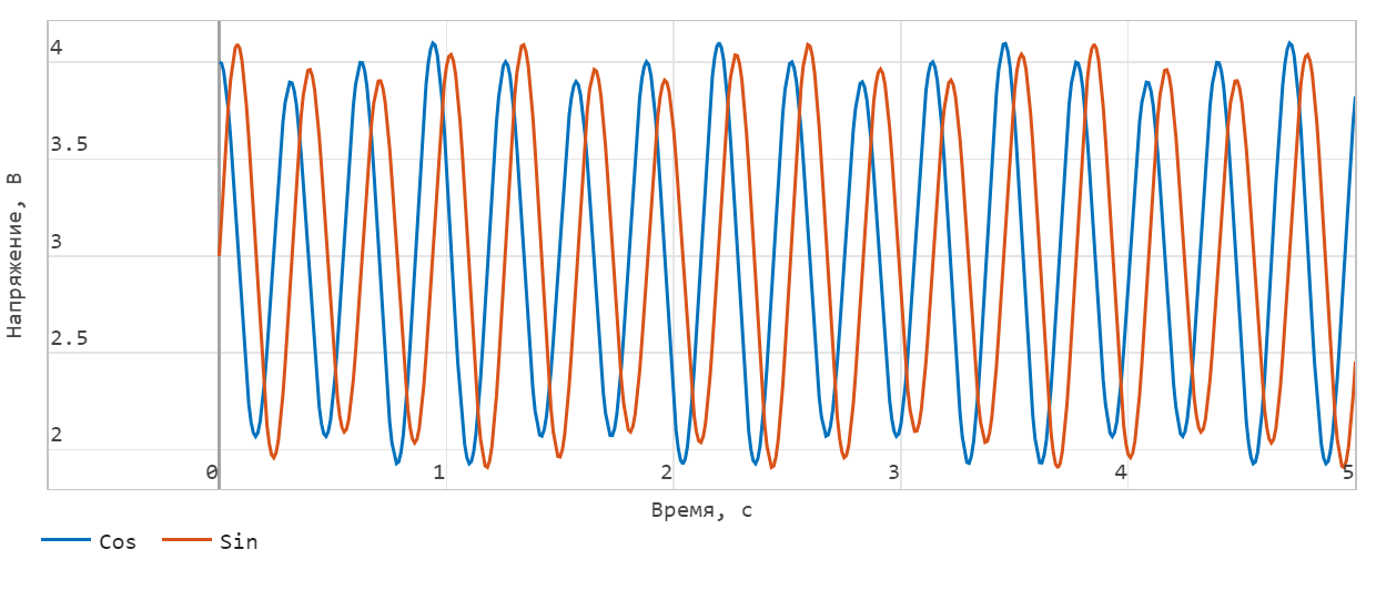
The decoding of the angle is calculated using the formula:
This figure shows the effect of the instability coefficient.:
Variables
Use the parameter group Initial Targets to set the priority and initial target values for the block parameter variables before modeling. For more information, see Configuring physical blocks using target values.
Ports
Conserving
#
R
—
sensor shaft
rotational mechanics
Details
A mechanical rotation port corresponding to the positive connection of the sensor.
| Program usage name |
|
#
C
—
sensor housing
rotational mechanics
Details
The mechanical rotation port corresponding to the negative (reference) connection of the sensor.
| Program usage name |
|
#
yp
—
positive axis terminal
electricity
Details
The electrical port connected to the positive terminal of the axis .
Dependencies
To use this port, set the parameter Output interface meaning Electrical connections.
| Program usage name |
|
#
yn
—
the negative terminal of the axis
electricity
Details
Electrical port connected to the negative terminal of the axis .
Dependencies
To use this port, set the parameter Output interface meaning Electrical connections.
| Program usage name |
|
#
xp
—
positive axis terminal
electricity
Details
The electrical port connected to the positive terminal of the axis .
Dependencies
To use this port, set the parameter Output interface meaning Electrical connections.
| Program usage name |
|
#
xn
—
negative terminal of the axis
electricity
Details
Electrical port connected to the negative terminal of the axis .
Dependencies
To use this port, set the parameter Output interface meaning Electrical connections.
| Program usage name |
|
Output
#
Angle
—
angle of rotation, rad
scalar
Details
The angle of rotation of the magnetic field in the plane - , is returned as a scalar.
Dependencies
To use this port, set the parameter Output interface meaning Decoded angular position
| Data types |
|
| Complex numbers support |
No |
Parameters
Parameters
# Number of pole pairs — number of pairs of poles
Details
The number of pairs of poles.
| Default value |
|
| Program usage name |
|
| Evaluatable |
Yes |
#
X-axis voltage amplitude —
tension along the axis
V | uV | mV | kV | MV
Details
Voltage amplitude along the axis .
| Units |
|
| Default value |
|
| Program usage name |
|
| Evaluatable |
Yes |
#
Y-axis voltage amplitude —
tension along the axis
V | uV | mV | kV | MV
Details
Voltage amplitude along the axis .
| Units |
|
| Default value |
|
| Program usage name |
|
| Evaluatable |
Yes |
#
X-axis voltage offset —
voltage shift along the axis
V | uV | mV | kV | MV
Details
Potential difference when an electric current flows through a conductor in the absence of an external magnetic field along the axis .
| Units |
|
| Default value |
|
| Program usage name |
|
| Evaluatable |
Yes |
#
Y-axis voltage offset —
voltage shift along the axis
V | uV | mV | kV | MV
Details
Potential difference when an electric current flows through a conductor in the absence of an external magnetic field along the axis .
| Units |
|
| Default value |
|
| Program usage name |
|
| Evaluatable |
Yes |
#
Quadrature error —
quadrature error
rad | deg | rev | mrad | arcsec | arcmin | gon
Details
The magnitude of the quadrature error. Quadrature switching can reduce bias errors.
| Units |
|
| Default value |
|
| Program usage name |
|
| Evaluatable |
Yes |
# Tumbling coefficient — coefficient of instability
Details
The coefficient of instability.
| Default value |
|
| Program usage name |
|
| Evaluatable |
Yes |
#
Output interface —
interface for decoded information
Electrical connections | Decoded angular position
Details
Interface for decoded information, available values:
-
Electrical connections. -
Decoded angular position.
| Values |
|
| Default value |
|
| Program usage name |
|
| Evaluatable |
No |