Double-Acting Servo Valve Actuator (IL)
A double-acting hydraulic booster cylinder with a spring-return spool in an isothermal fluid system.
blockType: EngeeFluids.IsothermalLiquid.Valves.Controls.DoubleActingServoActuator
|
Path in the library: |

Description
Block Double-Acting Servo Valve Actuator (IL) simulates a double-acting hydraulic booster cylinder made in the form of a spool with a spring return to the middle position. The neutral position of the spring corresponds to the middle stroke of the spool. The movement of the piston when it is almost fully extended or fully retracted is limited to one of the four stop patterns. The compressibility of the liquid is additionally modeled in both chambers of the piston.
The non-directional output signal S indicates the position of the spool.
The stop model
To avoid mechanical damage to the actuator when fully extended or retracted, the actuator usually exhibits non-linear behavior when the piston approaches these limits. Block Double-Acting Servo Valve Actuator (IL) simulates this behavior using a choice of four stop models that simulate the ductility of the material through a spring-damping system. Stop models:
-
Stiffness and damping applied smoothly through transition region, damped rebound. -
Full stiffness and damping applied at bounds, undamped rebound. -
Full stiffness and damping applied at bounds, damped rebound. -
Based on coefficient of restitution.
The thrust force is modeled when the piston is at the upper or lower limit. The boundary area is located within Transition region the parameter Spool stroke or the initial displacement of the piston. Outside of this area .
For more information about these settings, see the block page. Translational Hard Stop.
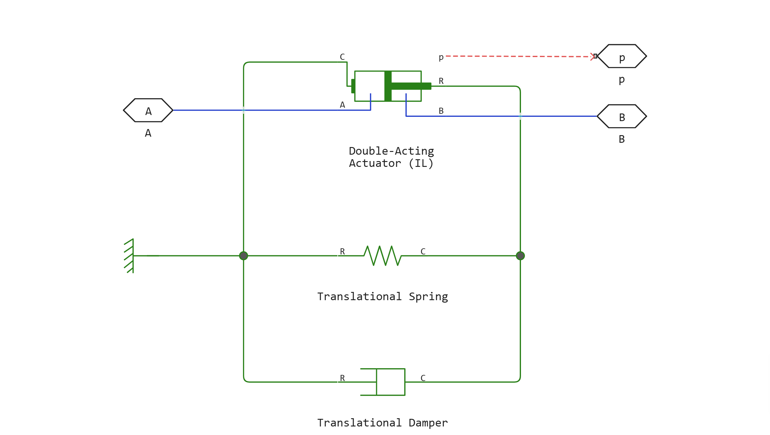
The block diagram
Block Double-Acting Servo Valve Actuator (IL) it consists of one library block Isothermal Liquid and two library blocks Fundamental:
Ports
Conserving
#
B
—
non-directional port for camera B
Isothermal liquid
Details
A non-directional port connected to the fluid inlet of chamber B.
| Program usage name |
|
#
A
—
non-directional port for camera A
Isothermal liquid
Details
A non-directional port connected to the fluid inlet of chamber A.
| Program usage name |
|
Output
#
S
—
position of the spool, m
scalar
Details
A non-directional signal associated with the position of the spool, measured in meters. The zero position indicates that the spool is in the neutral position in the middle of the stroke.
| Data types |
|
| Complex numbers support |
I don’t |
Parameters
Effects and Initial Conditions
#
Initial liquid pressure in chamber A —
liquid pressure
Pa | uPa | hPa | kPa | MPa | GPa | kgf/m^2 | kgf/cm^2 | kgf/mm^2 | mbar | bar | kbar | atm | ksi | psi | mmHg | inHg
Details
The pressure in the drive chamber A at the beginning of the simulation.
Dependencies
To use this option, check the box next to the option Fluid dynamic compressibility.
| Units |
|
| Default value |
|
| Program usage name |
|
| Evaluatable |
Yes |
#
Initial liquid pressure in chamber B —
liquid pressure
Pa | uPa | hPa | kPa | MPa | GPa | kgf/m^2 | kgf/cm^2 | kgf/mm^2 | mbar | bar | kbar | atm | ksi | psi | mmHg | inHg
Details
The pressure in the drive chamber B at the beginning of the simulation.
Dependencies
To use this option, check the box next to the option Fluid dynamic compressibility.
| Units |
|
| Default value |
|
| Program usage name |
|
| Evaluatable |
Yes |
#
Spool initial displacement —
the initial position of the spool
m | um | mm | cm | km | in | ft | yd | mi | nmi
Details
If the initial displacement of the spool is 0, the spool is located directly between chambers A and B. A positive distance value moves the spool away from camera A, and a negative one moves it towards camera A.
| Units |
|
| Default value |
|
| Program usage name |
|
| Evaluatable |
Yes |
# Fluid dynamic compressibility — compressibility of the liquid
Details
Should any changes in the density of the liquid be modeled due to the compressibility of the liquid. If next to the parameter Fluid dynamic compressibility If the check box is selected, changes related to the mass flow rate of the fluid in the unit are calculated in addition to density changes related to pressure changes. In the library Isothermal Liquid all blocks calculate the density depending on the pressure.
| Default value |
|
| Program usage name |
|
| Evaluatable |
No |
Cylinder
#
Spool cross-sectional area —
measuring the area
m^2 | um^2 | mm^2 | cm^2 | km^2 | in^2 | ft^2 | yd^2 | mi^2 | ha | ac
Details
The cross-sectional area of the spool.
| Units |
|
| Default value |
|
| Program usage name |
|
| Evaluatable |
Yes |
#
Damping coefficient —
damping coefficient
N*s/m | kgf*s/m | lbf*s/ft | lbf*s/in
Details
The damping coefficient in the contact area of the piston with the housing.
| Units |
|
| Default value |
|
| Program usage name |
|
| Evaluatable |
Yes |
#
Spring stiffness —
spring stiffness
N/m | mN/m | kN/m | MN/m | GN/m | kgf/m | lbf/ft | lbf/in
Details
The rigidity of the centering springs.
| Units |
|
| Default value |
|
| Program usage name |
|
| Evaluatable |
Yes |
#
Spool stroke —
distance
m | um | mm | cm | km | in | ft | yd | mi | nmi
Details
The distance that the spool travels in one stroke.
| Units |
|
| Default value |
|
| Program usage name |
|
| Evaluatable |
Yes |
Hard Stop
#
Static contact speed threshold —
the threshold value of the relative velocity between the slider and the stop before the collision
m/s | mm/s | cm/s | km/s | m/hr | km/hr | in/s | ft/s | mi/s | ft/min | mi/hr | kn
Details
The threshold value of the relative velocity between the slider and the stop before the collision. When the slider hits the housing at a speed lower than the parameter value Static contact speed threshold they stay in contact. Otherwise, the slider bounces. To avoid simulating static contact of the slider with the housing, set this parameter to 0.
Dependencies
To use this parameter, set for the parameter Hard stop model meaning Based on coefficient of restitution.
| Units |
|
| Default value |
|
| Program usage name |
|
| Evaluatable |
Yes |
#
Hard stop model —
choosing a stop model
Stiffness and damping applied smoothly through transition region, damped rebound | Full stiffness and damping applied at bounds, undamped rebound | Full stiffness and damping applied at bounds, damped rebound | Based on coefficient of restitution
Details
Selecting the model of the force acting on the piston when fully extended or fully retracted. For more information, see the block page Translational Hard Stop.
| Values |
|
| Default value |
|
| Program usage name |
|
| Evaluatable |
No |
#
Hard stop stiffness coefficient —
stiffness coefficient
N/m | mN/m | kN/m | MN/m | GN/m | kgf/m | lbf/ft | lbf/in
Details
The coefficient of piston stiffness.
Dependencies
To use this parameter, set for the parameter Hard stop model one of the following values:
-
Stiffness and damping applied smoothly through transition region, damped rebound; -
Full stiffness and damping applied at bounds, undamped rebound; -
Full stiffness and damping applied at bounds, damped rebound.
| Units |
|
| Default value |
|
| Program usage name |
|
| Evaluatable |
Yes |
#
Static contact release force threshold —
the threshold value of the force required to switch from contact mode to free mode
N | nN | uN | mN | kN | MN | GN | dyn | lbf | kgf
Details
The minimum force required to remove the slider from static contact mode.
Dependencies
To use this parameter, set for the parameter Hard stop model meaning Based on coefficient of restitution.
| Units |
|
| Default value |
|
| Program usage name |
|
| Evaluatable |
Yes |
#
Transition region —
the range of application of the force model in the stop
m | um | mm | cm | km | in | ft | yd | mi | nmi
Details
The range of application of the force model in the stop. Outside the range of maximum extension and maximum retraction of the piston parameter Hard stop model it is not applied, and the piston is not affected by additional force.
Dependencies
To use this parameter, set for the parameter Hard stop model meaning Stiffness and damping applied smoothly through transition region, damped rebound.
| Units |
|
| Default value |
|
| Program usage name |
|
| Evaluatable |
Yes |
#
Hard stop damping coefficient —
damping coefficient
N*s/m | kgf*s/m | lbf*s/ft | lbf*s/in
Details
Piston damping coefficient.
Dependencies
To use this parameter, set for the parameter Hard stop model one of the following values:
-
Stiffness and damping applied smoothly through transition region, damped rebound; -
Full stiffness and damping applied at bounds, undamped rebound; -
Full stiffness and damping applied at bounds, damped rebound.
| Units |
|
| Default value |
|
| Program usage name |
|
| Evaluatable |
Yes |
# Coefficient of restitution — the ratio of the final and initial relative velocity between the slider and the stop after the collision
Details
The ratio of the final and initial relative velocity between the slider and the stop after the slider rebounds.
Dependencies
To use this parameter, set for the parameter Hard stop model meaning Based on coefficient of restitution.
| Default value |
|
| Program usage name |
|
| Evaluatable |
Yes |