Flash ADC
N-bit ADC with flash architecture.
blockType: SubSystem
|
Path in the library: |
Description
Block Flash ADC It is a ladder−type resistor circuit containing 2N resistors and 2N-1 comparators.
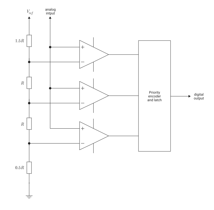
The reference voltage of each comparator is higher by one Least Significant Bit (LSB) than that of the next comparator in the ladder circuit. As a result, all comparators below a certain point will have an input voltage greater than the reference voltage and a logical output signal. 1. All comparators above this point will have an input voltage lower than the reference voltage and a logical output signal. 0. The output signals of 2N−1 comparators pass through a priority encoder to obtain a digital output signal. This encryption scheme is called thermometric encoding.
Since the analog input signal is applied to all comparators simultaneously, the architecture of the block Flash ADC very fast. However, analog-to-digital conversion (ADC) has low resolution and high power consumption requirements due to the large number of resistors required to implement the architecture.
Ports
Input
#
analog
—
analog input signal
scalar
Details
An analog input signal specified as a scalar.
| Data types |
|
| Complex numbers support |
No |
#
start
—
external clock signal for the start of conversion
scalar
Details
The external clock signal of the conversion start, set as a scalar. The analog-to-digital conversion process begins with the rising edge of the signal on the start port.
Dependencies
To use this port, check the box Use external start clock.
| Data types |
|
| Complex numbers support |
No |
Output
#
digital
—
converted digital output signal
scalar
Details
The converted digital output signal returned as a scalar.
| Data types |
|
| Complex numbers support |
No |
#
ready
—
determines whether the analog-to-digital conversion is completed
scalar
Details
The signal that determines whether the analog-to-digital conversion is completed, returned as a scalar.
| Data types |
|
| Complex numbers support |
No |
Parameters
Configuration
Main
# Number of bits — number of physical output bits
Details
The number of physical output bits specified as a dimensionless positive integer in the range [1, 26]. This parameter determines the resolution of the ADC.
| Default value |
|
| Program usage name |
|
| Tunable |
No |
| Evaluatable |
Yes |
# Input range (V) — dynamic range of the ADC
Details
The dynamic range of the ADC, specified as a two-element vector string in volts.
| Default value |
|
| Program usage name |
|
| Tunable |
No |
| Evaluatable |
Yes |
Conversion Start Clock
# Use external start clock — the ability to connect to an external clock signal for the start of conversion
Details
Select this option to connect to an external clock signal to start the conversion. This option is enabled by default.
| Default value |
|
| Program usage name |
|
| Tunable |
No |
| Evaluatable |
Yes |
# Conversion start frequency (Hz) — the frequency of the internal clock signal for the start of conversion
Details
The frequency of the internal clock signal of the conversion start, set as a positive real scalar in Hz. This parameter determines the speed of the ADC.
Dependencies
To use this option, uncheck the box. Use external start clock.
| Default value |
|
| Program usage name |
|
| Tunable |
No |
| Evaluatable |
Yes |
# RMS aperture jitter (s) — description missing
Details
description missing
| Default value |
|
| Program usage name |
|
| Tunable |
No |
| Evaluatable |
Yes |
Main
#
Edge trigger type —
the type of clock edge that triggers the output signal update
Rising edge | Falling edge | Either edge
Details
The type of clock edge that triggers the output signal update:
-
Rising edge— The output signal is updated along the rising edge of the clock signal. -
Falling edge— the output signal is updated on the falling edge of the clock signal. -
Either edge— the output signal is updated both along the rising and falling edges of the clock signal.
| Values |
|
| Default value |
|
| Program usage name |
|
| Tunable |
No |
| Evaluatable |
Yes |
Output Options
# Match input scale — the ability to inherit the polarity and data type of the output signal from the input
Details
The ability to inherit the polarity and data type of the output signal from the analog input signal of the ADC. If this option is selected, the ADC will ignore the parameters. Output Polarity and Output data type. The output signal of the ADC will have the same polarity as the input, and the data type will be Float64.
| Default value |
|
| Program usage name |
|
| Tunable |
No |
| Evaluatable |
Yes |
#
Output Polarity —
determining the polarity of the ADC output signal
Auto | Bipolar | Unipolar
Details
Determine the polarity of the ADC output:
-
Auto— the minimum and maximum values of the output signal are determined by the polarity of the parameter Input range (V). -
Bipolar— the output values are in the range of−2NBits−1before2NBits−1 − 1. -
Unipolar— the output values are in the range of0before2NBits−1.
Dependencies
To use this option, uncheck the box. Match input scale.
| Values |
|
| Default value |
|
| Program usage name |
|
| Tunable |
No |
| Evaluatable |
Yes |
#
Output data type —
determining the type of ADC output data
Float64 | Float32 | UInt8 | UInt16 | UInt32 | fixdt(0, NBits) | Inherit: Inherit via back propagation
Details
Determine the type of ADC output:
-
Float64; -
Float32; -
Int8; -
Int16; -
Int32; -
fixdt(0, NBits)— unsigned integers and fixed-point types; -
Inherit: Inherit via back propagation.
Dependencies
To use this option, uncheck the box. Match input scale, and for the parameter Output Polarity set the value Unipolar.
| Values |
|
| Default value |
|
| Program usage name |
|
| Tunable |
No |
| Evaluatable |
Yes |
#
Output data type —
determining the type of ADC output data
Float64 | Float32 | Int8 | Int16 | Int32 | fixdt(1, NBits) | Inherit: Inherit via back propagation
Details
Determine the type of ADC output:
-
Float64; -
Float32; -
Int8; -
Int16; -
Int32; -
fixdt(1, NBits)— signed integers and fixed-point types; -
Inherit: Inherit via back propagation.
Dependencies
To use this option, uncheck the box. Match input scale, and for the parameter Output Polarity set the value Bipolar or Auto.
| Values |
|
| Default value |
|
| Program usage name |
|
| Tunable |
No |
| Evaluatable |
Yes |
Impairments
Main
# Enable Linearity Impairments — the ability to include linearity distortion in ADC modeling
Details
Check this box to enable linearity distortion, such as Offset error and Gain error, in ADC simulation. This option is unchecked by default.
| Default value |
|
| Program usage name |
|
| Tunable |
No |
| Evaluatable |
Yes |
Linearity Impairments
# Offset error — shifting the quantization steps by a preset value
Details
The parameter allows you to shift the quantization steps by a certain value, set as a scalar in %FS, FS or LSB.
|
The full scale range of the converter is defined as the difference between the last and the first code on the compensated transfer curve. Meaning |
Dependencies
To use this option, check the box Enable Linearity Impairments on the tab Impairments.
| Default value |
|
| Program usage name |
|
| Tunable |
No |
| Evaluatable |
Yes |
#
Offset error measurement unit —
units of measurement for shifting quantization steps
%FS | FS | LSB
Details
Select the units of measurement for the parameter value Offset error: %FS, FS or LSB.
Dependencies
To use this option, check the box Enable Linearity Impairments on the tab Impairments.
| Values |
|
| Default value |
|
| Program usage name |
|
| Tunable |
No |
| Evaluatable |
Yes |
# Gain error — ADC transfer curve tilt error
Details
The slope error of a straight line interpolating the ADC transfer curve, set as a scalar in %FS, FS or LSB.
|
The full scale range of the converter is defined as the difference between the last and the first code on the compensated transfer curve. Meaning |
Dependencies
To use this option, check the box Enable Linearity Impairments on the tab Impairments.
| Default value |
|
| Program usage name |
|
| Tunable |
No |
| Evaluatable |
Yes |
#
Gain error measurement unit —
units of measurement for the slope error of the ADC transfer curve
%FS | FS | LSB
Details
Select the measurement units for the parameter value Gain error: %FS, FS or LSB.
Dependencies
To use this option, check the box Enable Linearity Impairments on the tab Impairments.
| Values |
|
| Default value |
|
| Program usage name |
|
| Tunable |
No |
| Evaluatable |
Yes |
# Missing codes — positions of faulty comparators
Details
The positions of the faulty comparators, specified as a vector string of positive real values.
Dependencies
To use this option, check the box Enable Linearity Impairments on the tab Impairments.
| Default value |
|
| Program usage name |
|
| Tunable |
No |
| Evaluatable |
Yes |
Main
# Enable Timing Impairments — the ability to include time distortion in ADC modeling
Details
Check this box to enable time distortion, such as Conversion delay (s), in ADC simulation. This option is unchecked by default.
| Default value |
|
| Program usage name |
|
| Tunable |
No |
| Evaluatable |
Yes |
Timing Impairments
# Conversion delay (s) — ADC delay
Details
The delay of the analog-to-digital converter, set as a non-negative real scalar in seconds.
Dependencies
To use this option, check the box Enable Timing Impairments on the tab Impairments.
| Default value |
|
| Program usage name |
|
| Tunable |
No |
| Evaluatable |
Yes |
# Enable increased buffer size — the ability to enable an increased buffer size
Details
Select this option to enable the increased buffer size during simulation. This option is unchecked by default.
Dependencies
To use this option, check the box Enable Timing Impairments on the tab Impairments.
| Default value |
|
| Program usage name |
|
| Tunable |
No |
| Evaluatable |
Yes |
# Buffer size — number of additional buffer filters
Details
The number of additional buffer filters available during the simulation, set as a positive real scalar.
Choosing different simulation solvers or sampling strategies can change the number of input samples needed to obtain an accurate output sample. Set this parameter to a value large enough so that the input buffer contains all the necessary input samples.
Dependencies
To use this option, check the boxes Enable Timing Impairments and Enable increased buffer size on the tab Impairments.
| Default value |
|
| Program usage name |
|
| Tunable |
No |
| Evaluatable |
Yes |