EngeeRF.rfdivider
Creates a Wilkinson three-port power divider element for an object circuit.
| Library |
|
Description
Use the system object EngeeRF.rfdivider to create a three-port Wilkinson power divider element. You can add this element to an object. circuit to create a radio frequency (RF) circuit.
Syntax
Creation
-
rfpd = EngeeRF.rfdivider()— creates a Wilkinson three-port power divider object with default properties.
-
rfpd = EngeeRF.rfdivider(Name=Value)— creates a Wilkinson three-port power divider system objectrfpdwith properties set as a pairName=Value, whereName— the name of the property, andValue— the appropriate value. You can specify multiple pairs «name-value» the order of the pairs does not matter. Unspecified properties retain their default values.Example:
rfpd = EngeeRF.rfdivider(Impedance = 75)creates a three-port Wilkinson power divider object with an impedance75Om.
Arguments
Output arguments
# rfpd is a Wilkinson power divider object
+
object
Details
A Wilkinson power divider object containing the following properties:
-
Impedance— characteristic impedance; -
Name— the name of the object as a string, for example"Divider"; -
Ports— port names as a tuple of strings:("p1", "p2", "p3"); -
Terminals— terminal names in the form of a tuple of strings; -
ParentNodes— nodes of the parent schema in the form of a vector of integers, displayed only after adding the child schema to the parent schema; -
ParentPath— the full path to the parent schema as a string, displayed only after adding the child schema to the parent schema.; -
NumPorts— number of ports; -
Parent— the parent circuit that the chain object belongs to.
Features
# Impedance is the characteristic impedance of the Wilkinson power divider element, ohms
+
50.0 (by default) | scalar
Details
The characteristic impedance of the Wilkinson power divider element in ohms, set as a positive scalar.
| Типы данных |
|
# Name is the name of the Wilkinson power divider element
+
"Divider" (by default) | line
Details
The name of the Wilkinson power divider element, set as a string.
| Типы данных |
|
# Terminals — terminal names of the Wilkinson power divider element
+
("p1+", "p2+", "p3+", "p1−", "p2−", "p3−") (by default) | tuple of strings
Details
The terminal names of the Wilkinson power divider element, set as a tuple of strings.
| This property is read-only. |
# NumPorts — number of input and output ports
+
3 (by default) | scalar
Details
The number of input and output ports, set as a positive scalar.
| This property is read-only. |
| Типы данных |
|
Methods
sparameters: Calculation of S-parameters for radio frequency data, networks, circuits and related objects
circuit:: Creating an electrical circuit diagram object
clone:: Creating a copy of an existing schema element or schema object
Examples
Adding a Wilkinson Power Divider element to a circuit object
Details
Let’s create a Wilkinson power divider element with three ports with default properties.
import EngeeRF: rfdivider

pd = rfdivider(Name = "rfdivider1")
Let’s create a copy of the Wilkinson three-port power divider element.
import EngeeRF: clone

pd2 = clone(pd)
pd2.Name = "rfdivider2"
Creating an amplifier element with a gain factor 12 dB.
import EngeeRF: amplifier

amp = amplifier(Name = "amplifier1", Gain = 12)
Create a copy of the amplifier element.
amp2 = clone(amp)
amp2.Name = "amplifier2"
Creating an object circuit.
import EngeeRF: circuit

ckt = circuit()
Add a divider with the name rfdivider1 to the object circuit.
import EngeeRF: add

add(ckt, [1 2 3], pd)
Add an amplifier with the name amplifier1 to the object circuit.
add(ckt, [2 4], amp)Add an amplifier with the name amplifier2 to the object circuit.
add(ckt, [3 5], amp2)Add a divider with the name rfdivider2 to the object circuit.
add(ckt, [6 4 5], pd2)Using the function setports to configure the object ports circuit.
import EngeeRF: setports

setports(ckt, [1 0], [6 0], ("in", "out"))
Let’s output the properties of the object circuit.
println("ElementNames: ", ckt.ElementNames,
        "\nElements: ", ckt.Elements,
        "\nName: ", ckt.Name,
        "\nNodes: ", ckt.Nodes,
        "\nNumPorts: ", ckt.NumPorts,
        "\nPorts: ", ckt.Ports,
        "\nTerminalNodes: ", ckt.TerminalNodes,
        "\nTerminals: ", ckt.Terminals)
ElementNames: ("rfdivider1", "amplifier1", "amplifier2", "rfdivider2")
Elements: EngeeRF.DomainRF.DomainObjectRF[rfdivider(Impedance = 50.0, Name = "rfdivider1", Ports = ("p1", "p2", "p3"), Terminals = ("p1+", "p2+", "p3+", "p1-", "p2-", "p3-"), ParentNodes = [1, 2, 3, 0, 0, 0], ParentPath = "unnamed", NumPorts = 3), amplifier(Model = "cubic", Name = "amplifier1", ParentNodes = [2, 4, 0, 0], ParentPath = "unnamed", Gain = 12.0, NF = 0.0, OIP2 = Inf, OIP3 = Inf, Zin = 50.0 + 0.0im, Zout = 50.0 + 0.0im), amplifier(Model = "cubic", Name = "amplifier2", ParentNodes = [3, 5, 0, 0], ParentPath = "unnamed", Gain = 12.0, NF = 0.0, OIP2 = Inf, OIP3 = Inf, Zin = 50.0 + 0.0im, Zout = 50.0 + 0.0im), rfdivider(Impedance = 50.0, Name = "rfdivider2", Ports = ("p1", "p2", "p3"), Terminals = ("p1+", "p2+", "p3+", "p1-", "p2-", "p3-"), ParentNodes = [6, 4, 5, 0, 0, 0], ParentPath = "unnamed", NumPorts = 3)]
Name: unnamed
Nodes: [0, 1, 2, 3, 4, 5, 6]
NumPorts: 2
Ports: ("in", "out")
TerminalNodes: [1, 6, 0, 0]
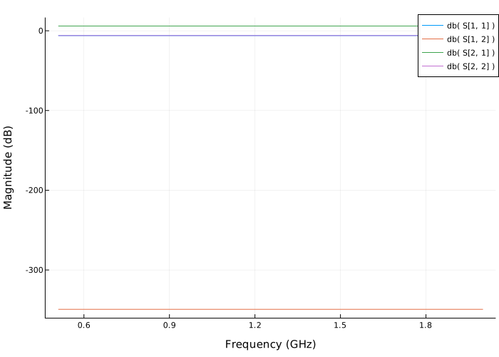
Terminals: ("in+", "out+", "in-", "out-")Let’s plot the S-parameters of the circuit for the frequency range. 0.51–2 GHz.
import EngeeRF: sparameters, rfplot

freq = range(0.51e9, 2e9, length=11)
sparam = sparameters(ckt, freq)
rfplot(sparam)