CIC Decimation
Decimation of the signal using a cascade integrator-comb filter.
blockType: CICDecimation
|
Path in the library: |

Description
Block CIC Decimation reduces the sampling rate (decimation) of the input signal by an integer factor. Cascade CIC filters are a class of linear phase FIR filters consisting of cascaded comb filters and integrators.
The unit supports real and complex fixed-point input signals. In the normal operation mode of the unit CIC Decimation when the adders overflow, a cyclic transfer is performed, in which the countdown continues from the minimum value when overflowing from above and the maximum value when overflowing from below. For more information, see [1] and [3]. Overflow does not affect further signal processing processes.
Ports
Output
#
OUT_1
—
decimated output signal
vector | the matrix
Details
The output signal decimated by the CIC filter is returned as a vector or matrix. The output data type is determined by the block parameter settings. The complexity of the output data corresponds to the complexity of the input.
The number of output lines is , where — the decimation coefficient, and — number of input lines.
| Data types |
|
| Complex numbers support |
Yes |
Input
#
IN_1
—
Input signal
vector | the matrix
Details
An input signal specified as a vector or matrix. The number of input lines must be a multiple of the decimation factor.
| Data types |
|
| Complex numbers support |
Yes |
Parameters
Main
#
Coefficient source —
source of information about the filter
Dialog parameters
Details
-
Dialog parameters— entering information about the filter in the dialog box of the block. For example, through the parameters Decimation coefficient (R), Differential delay (M) and Number of sections (N).
| Values |
|
| Default value |
|
| Program usage name |
|
| Tunable |
No |
| Evaluatable |
No |
#
Decimation factor (R) —
decimation coefficient
Real number
Details
The decimation coefficient of the filter, set as an integer greater than 1.
| Default value |
|
| Program usage name |
|
| Tunable |
No |
| Evaluatable |
Yes |
#
Differential delay (M) —
differential delay
Real number
Details
Set the differential delay of the comb filter as a positive integer.
| Default value |
|
| Program usage name |
|
| Tunable |
No |
| Evaluatable |
Yes |
#
Number of sections (N) —
number of filter sections
Real number
Details
Specify the number of filter sections. The specified number determines both the number of sections in the comb filter and the number of integrators, but not these values combined.
| Default value |
|
| Program usage name |
|
| Tunable |
No |
| Evaluatable |
Yes |
#
Data type specification mode —
a method for specifying the length of a word and the length of the fractional part of fixed-point numbers for filter sections and output signal
Full precision
Details
A method for specifying the length of a word and the length of the fractional part of fixed-point numbers for filter sections and/or output, specified as:
-
Full precision— Word lengths and fractional lengths of fixed-point numbers for filter and output sections are selected automatically. The word lengths of the output signal/output and the last section installed as:Where
-
— input word length;
-
— differential delay;
-
— number of sections;
-
— interpolation coefficient.
-
The word lengths of other sections are set taking into account the growth of bits, as described in the work of Hogenauer [1]. The lengths of all fractional parts are set equal to the fractional part of the input signal.
| Values |
|
| Default value |
|
| Program usage name |
|
| Tunable |
No |
| Evaluatable |
No |
#
Rate options —
signal processing mode
Enforce single-rate processing
Details
The input signal processing mode specified as:
-
Enforce single-rate processing— The unit stores the sampling rate of the input signal.
| Values |
|
| Default value |
|
| Program usage name |
|
| Tunable |
No |
| Evaluatable |
No |
Additional Info
CIC filter
Details
CIC filter is an optimized class of linear—phase FIR filters consisting of cascaded comb filters and integrators.
Conceptually, the decimation CIC filter is a CIC filter , which is a reconstructive low-pass filter and performs filtering without changing the sampling rate, followed by an element of lowering the sampling rate. Block CIC Decimation reduces the sampling rate of the input signal by an integer factor using a Cascaded Integrator comb filter (CIC).

In a more efficient implementation, a CIC filter that works without changing the sampling frequency, it is decomposed into factors in this way:
where
-
— the transfer function of the cascade of integrators;
-
— transfer function sections of a cascade of comb filters, each of which has a width of ;
-
— the number of sections. The number of sections in a CIC filter is defined as the number of sections either in the comb part or in the integrating part of the filter. This value does not reflect the total number of sections in the entire filter.;
-
— the decimation coefficient;
-
— differential delay.
The algorithm that provides full multi-rate filtering takes into account two remarkable identities for interpolation, which allow you to move the operation of changing the sampling frequency. for the cascade of comb filters without distorting the result of the operation.
The transfer function of the resulting filter is given by the following equation:
For a flowchart showing multi-speed implementation, see [algorithms].
Algorithms
Decimation CIC filter
Details
The decimation CIC filter is implemented as a cascade of integrators, followed by an element of lowering the sampling rate of the signal in once, and then a cascade of comb filters.
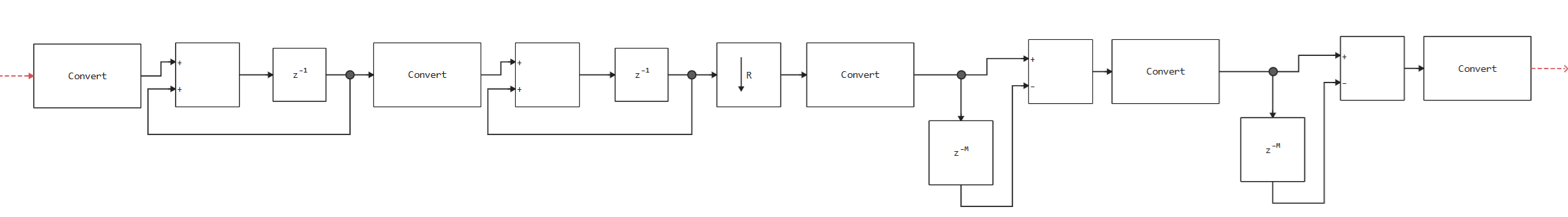
The diagram shows a cascade of integrators with two sections and a cascade of comb filters, also consisting of two sections. The single delay in the CIC filter integrators can be located in both the forward and feedback circuits. These two configurations produce identical filter frequency characteristics. However, the actual numerical sequences in the output for these two configuration options will be different due to the effect of the delay. In this algorithm, a single delay is placed in the path of the direct line of the integrator, since this configuration is preferable for the HDL implementation.
Literature
-
Hogenauer, E.B. An Economical Class of Digital Filters for Decimation and Interpolation IEEE Transactions on Acoustics, Speech and Signal Processing. Vol. 29, Number 2, 1981, pp. 155–162, 1981.
-
Meyer-Baese, U. Digital Signal Processing with Field Programmable Gate Arrays. New York: Springer Verlag, 2001.
-
Harris, Fredric J., Multirate Signal Processing for Communication Systems. Upper Saddle River, NJ: Prentice Hall PTR, 2004.