Support package for managing the RITM SDR USRP hardware platform
The article contains information necessary for use in Engee libraries Targets.RITM_SDR_API designed for remote control of the RITM SDRfootnote hardware platform:[SDR (Software Defined Radio) is a software—defined radio.] USRP[1] and data exchange over an Ethernet network. The requirements for the runtime environment, the connection procedure, the description of the application programming interface (API) and the register map of the main IP cores are given. note:[IP core is a hardware functional module within the FPGA/SNC, accessible by address space.].
Purpose and conditions of use
Library Targets.RITM_SDR_API It is designed to control the RITM SDR USRP hardware platform based on the Xilinx Zynq UltraScale+ system-on-chip and the ADRV9009 RF transceiver. Management is carried out through network interaction with the RITM SDR USRP control module.
The SDR USRP RITM provides operation in the range of 75 MHz – 6 GHz with an instantaneous band up to 450 MHz. Library Targets.RITM_SDR_API It is used in the development, debugging and testing of wireless communication and radar systems.
General information
Library Targets.RITM_SDR_API implements a set of strongly typed Julia language methods and macros for performing the following operations:
-
establishing and terminating a TCP connection with the RITM SDR USRP control module;
-
setting radio frequency and path parameters (frequency, attenuation, TX/RXfootnote modes:[TX /RX — transmission/reception channels.]);
-
performing IP core reset and management procedures;
-
transmission and reception of I/Q samples and service data.
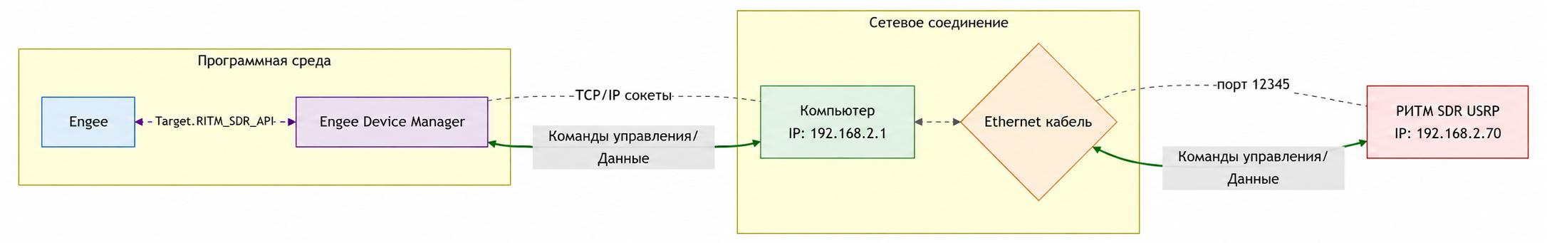
Interaction with the RITM SDR USRP is performed through Engee Device Manager. The diagram of the component interaction is shown in the figure.
Execution conditions
For the library to work Targets.RITM_SDR_API required:
-
RITM SDR USRP access to an Ethernet network;
-
availability Engee Device Manager on the side of the control computer (when used according to the accepted architecture).
Default Network settings:
-
IP address: SDR USRP —
192.168.2.70; -
TCP port —
12345.
Quick start
-
Install or connect the Engee subsystem.Integration as shown in article.
engee.package.install("Engee-Device-Manager")Connection link: engee.com/prod/user/demo1234-user Install the client program: https://dl.kpm-ritm.ru/repo/Host-Device-Manager-v1.57-Windows.zip - For Windows https://dl.kpm-ritm.ru/repo/Host-Device-Manager-v1.57-Linux.zip - For Linux To get examples, run: engee.package.getdemos("Engee-Device-Manager") To run the server program, run: engee.package.start("Engee-Device-Manager") The 'Engee-Device-Manager' support package, version 'v1.57', has been successfully installed.engee.package.start("Engee-Device-Manager")"engee.com/prod/user/demo1234-user" -
Use the commands:
using Main.EngeeDeviceManager.Targets.RITM_SDR_API
import Main.EngeeDeviceManager.Targets.RITM_SDR_API

client = RITM_SDR_API.RITMClient("192.168.2.70")
if !RITM_SDR_API.connect(client)
    println("Connection error")
    return
end
println("Server version: $(RITM_SDR_API.get_version(client))")
RITM_SDR_API.disconnect(client)
An example of the expected output to the console:
Connected to 192.168.2.70:12345
Server version: v5.1.5
Connection closed
For more information, see the article Getting started with the RITM SDR USRP
Application Programming Interface (API)
This section describes the macros and functions of the library. For each item, the name, prototype (if available in the source text) and purpose are indicated.
Logging Group
| Name | The prototype | Appointment |
|---|---|---|
|
|
A macro for «quiet» logging without output to the console. Records data only if |
|
|
The main switch of the logging system. Sets a global variable |
|
|
The main macro for combined output. Converts the expression to a string, clears it, prints it to the console, and if logging is active, writes it to a timestamped log file. Example: |
|
|
Prints a message to the console without a newline. It is used for interactive progress bars or displaying partial results in one line. |
|
|
Logging session ends correctly. Adds a final entry, creates a cleaned-up version of the log file, and resets global variables. |
Service functions
| Name | The prototype | Appointment |
|---|---|---|
|
|
Constructor of the main library object. Creates a structure with the following fields: the IP address of the control module, the TCP connection descriptor, and the sampling rate (by default). |
|
|
Clearing string responses from the control module of control and non-printable characters. |
|
|
Clearing the input buffer of the network socket. |
|
|
Receiving binary data from the control module according to the established protocol. |
|
|
Sending binary data to the control module using the established protocol. |
|
|
A key low-level function for sending commands to the control module. Sends a command, waits for processing, reads and analyzes the response. |
|
|
Secure disconnection. |
|
|
Establishing a TCP connection with the control module. The port is fixed — |
Managing basic parameters
| Name | The prototype | Appointment |
|---|---|---|
|
|
Request the calibration status of the system. |
|
|
Request for the current frequency. |
|
|
Request for a tabular value of receiver attenuation. |
|
|
Measuring the power at the receiver input. |
|
|
Request for the current status of the transceiver. |
|
|
Request for transmitter attenuation. |
|
|
Setting the carrier frequency of the transmitter and receiver. Checks the range, sends a command |
|
|
Universal parameter setting. |
|
|
Setting the tabular value of receiver attenuation. |
|
|
Configuration of the transmitter and receiver channels using bit masks. |
|
|
Setting the attenuation of the transmitter. |
|
|
Alternative frequency setting in Hz. |
|
|
Stopping the transmission. |
Advanced control and reset functions
| Name | Appointment |
|---|---|
|
Reading the register of the functional module (IP core). |
|
FIFOfootnote Target reset:[FIFO is a First In, First Out queue.] in the DFE system. |
|
Resetting the auxiliary noise generator unit. |
|
Resetting DMA Controllers note:[DMA (Direct Memory Access) — Direct memory access controller.] reception and transmission. |
|
Resetting the receiving and transmitting DMA controllers. |
|
Comprehensive FIFO buffer reset. |
|
Writing to the register of the functional module (IP core). |
RF switches
| Name | The prototype | Appointment |
|---|---|---|
|
|
Manual calibration of the feedback channel. |
|
|
RF switching control on a hardware platform. |
|
|
RF switching control on a hardware platform. |
|
|
RF switching control on a hardware platform. |
|
|
RF switching control on a hardware platform. |
|
|
RF switching control on a hardware platform. |
|
|
RF switching control on a hardware platform. |
|
|
Enabling/disabling the duplication of transmitter data for MIMO modes. |
Data reception and transmission management
| Name | Appointment |
|---|---|
|
Channel Attenuation Management ORX[2]. |
|
Checking the completion of the DMA transmission for the main reception (RX) and feedback channels (ORX). |
|
Checking the completion of the DMA transmission for the main reception (RX) and feedback channels (ORX). |
|
Formatting received data from |
|
Preparing complex data for transmission: scaling and interleaving of components. |
|
Receiving data from the feedback channel (ORX) into RAM. |
|
Initiates receiving data from the receiver into RAM. |
|
Direct switching on/off of receiving channels. |
|
The command to transfer data from RAM to the transmitter. |
|
ORX channel attenuation management. |
Additional service functions
| Name | Appointment |
|---|---|
|
Temperature monitoring of various components of the hardware platform. |
|
Request the software version of the control module. |
Automatic gain control functions
| Name | The prototype | Appointment |
|---|---|---|
|
|
Configuration of automatic gain control ( |
|
|
Force the automatic gain control settings to be applied after they have been changed. |
|
|
Reset the automatic gain control settings to the default values. |
|
|
Enabling/disabling the duplication of transmitter data for MIMO modes. |
Networking and data exchange
The connection to the control module of the product is established via TCP protocol. The port number is fixed (12345). Function connect() it must be called before executing any control and data exchange commands. Breaking the connection is performed by the function disconnect() (or close(), if a synonym is used).
Sending control commands is implemented through a low-level function _send_command(), which transmits a string command and analyzes the response. The transmission and reception of binary data arrays are performed by the functions _put_data() and _get_data() according to the established exchange protocol.
SDR Registers
The table shows the register map of IP cores available through the mechanism. set_ip_core()/get_ip_core(). Addresses are given in hexadecimal format. The data types are given in accordance with the designations used in the FPGA project.
| IP Core | Address (hex) | Register Name | Data Type | Description |
|---|---|---|---|---|
DUCex[3] |
|
|
|
Core Reset: Write |
DUCex |
|
|
|
The unique time stamp of the core (format |
DUCex |
|
|
|
The data register for setting the interpolation coefficient. |
DUCex |
|
|
|
Turning the interpolator on/off. |
DUCex |
|
|
|
Asynchronous core reset via AXI. |
DUCex |
|
|
|
Global core activation. |
DUCex |
|
|
|
Channel gain factor 0 (correction). |
DUCex |
|
|
|
Enabling channel 0 gain. |
DUCex |
|
|
|
Channel 1 gain (correction). |
DUCex |
|
|
|
Enabling channel 1 gain. |
DUCex |
|
|
|
Enabling NCO[4] channel 0. |
DUCex |
|
|
|
NCO Channel phase increment 0 ( |
DUCex |
|
|
|
The phase offset of the NCO channel is 0 ( |
DUCex |
|
|
|
Resetting the NCO phase drive of channel 0. |
DUCex |
|
|
|
NCO phase increment of Channel 1 ( |
DUCex |
|
|
|
NCO phase offset of channel 1 ( |
DUCex |
|
|
|
Reset the NCO phase drive of channel 1. |
DUCex |
|
|
|
Enabling NCO channel 1. |
DUCex |
|
|
|
Enabling DDS[5] channel 0. |
DUCex |
|
|
|
Enabling DDS channel 1. |
DDCex |
|
|
|
Core Reset: Write |
DDCex |
|
|
|
The unique time stamp of the core (format |
DDCex |
|
|
|
The data register for setting the decimation coefficient. |
DDCex |
|
|
|
Switching on/off the decimator. |
DDCex |
|
|
|
Asynchronous core reset via AXI[6]. |
DDCex |
|
|
|
Channel gain factor 0 (correction). |
DDCex |
|
|
|
Channel gain factor 1 (correction). |
DDCex |
|
|
|
Enabling channel 0 gain. |
DDCex |
|
|
|
Enabling channel 1 gain. |
DDCex |
|
|
|
The increment of the NCO phase of the channel is 0. |
DDCex |
|
|
|
The phase offset of the NCO channel is 0. |
DDCex |
|
|
|
Resetting the NCO phase drive of channel 0. |
DDCex |
|
|
|
The increment of the NCO phase of channel 1. |
DDCex |
|
|
|
The NCO phase offset of channel 1. |
DDCex |
|
|
|
Reset the NCO phase drive of channel 1. |
DDCex |
|
|
|
Enabling the NCO of the common output. |
DDCex |
|
|
|
Enabling NCO channel 1. |
DDCex |
|
|
|
Enabling DDS channel 0. |
DDCex |
|
|
|
Enabling DDS channel 1. |
DDCex |
|
|
|
|
DDCex |
|
|
|
|
DDCex |
|
|
|
|
DDCex |
|
|
|
|
DDCex |
|
|
|
|
DDCex |
|
|
|
|
DDCex |
|
|
|
|
DDCex |
|
|
|
|
DDCex |
|
|
|
|
DDCex |
|
|
|
|
DDCex |
|
|
|
|
DDCex |
|
|
|
|
AGCex[7] |
|
|
|
Core Reset: Write |
AGCex |
|
|
|
Enabling the kernel (enabled by default when bit 0 is equal to |
AGCex |
|
|
|
The unique time stamp of the core (format |
AGCex |
|
|
|
The data register for the input port |
AGCex |
|
|
|
The data register for the input port |
AGCex |
|
|
|
The data register for the input port |
AGCex |
|
|
|
The data register for the input port |
AGCex |
|
|
|
The data register for the input port |
AGCex |
|
|
|
The data register for the input port |
AGCex |
|
|
|
The data register for the input port |
AGCex |
|
|
|
The data register for the input port |
AGCex |
|
|
|
The data register for the input port |
AGCex |
|
|
|
The data register for the input port |
AGCex |
|
|
|
The data register for the input port |
AGCex |
|
|
|
The data register for the input port |
AGCex |
|
|
|
The data register for the input port |
AGCex |
|
|
|
The data register for the input port |
AGCex |
|
|
|
The data register for the output port |
AGCex |
|
|
|
The data register for the output port |
AGCex |
|
|
|
The data register for the output port |
AGCex |
|
|
|
The data register for the output port |
AGCex |
|
|
|
The data register for the output port. |