PWM Generator (3-Level)
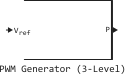
Pulse generation for a three-level converter with PWM control.
blockType: SubSystem
|
Path in the library: |
Description
Block PWM Generator (3-Level) generates pulses for a pulse width modulation (PWM) converter using a three-level topology. The unit can control switching devices (FET, GTO or IGBT) of three different types of converters: single-phase half-bridge (1 arm), single-phase full-bridge (2 arms) or three-phase bridge (3 arms).
The reference signal (Vref), also called the modulating signal, is naturally sampled and correlated with two symmetrical triangular carriers with a level shift.
The figure shows how pulses are generated for a single-phase semi-bridge three-level converter.
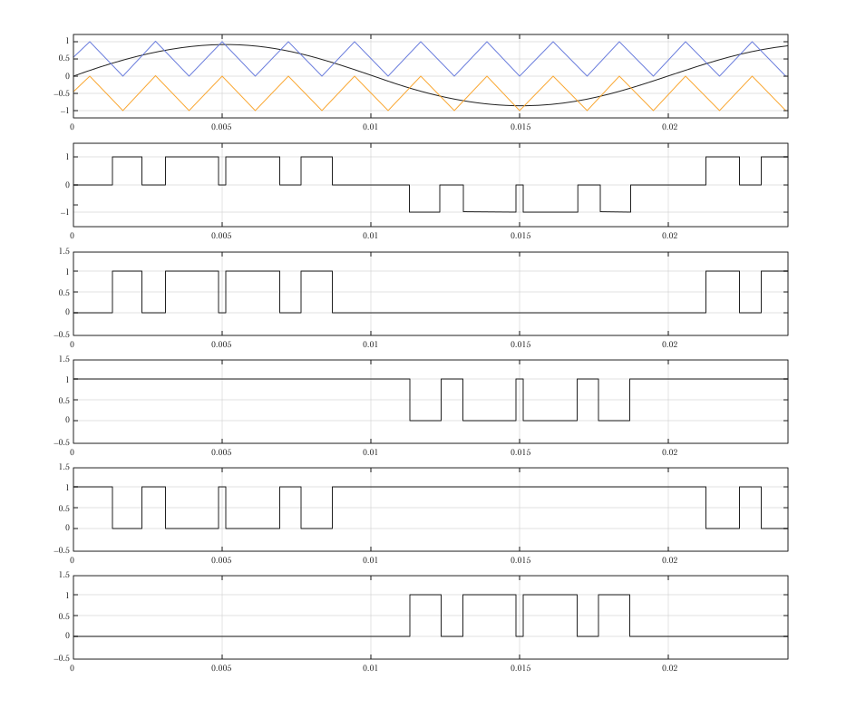
The converter arm can be in three states: +1, 0 or −1. When the reference signal is greater than the positive carrier, the shoulder condition is +1. When the reference signal is less than the negative carrier, the shoulder condition is −1. In all other cases, the status is 0. Depending on the current state of the shoulder, the unit generates corresponding pulses.
| Condition | Q1 | Q2 | Q3 | Q4 |
|---|---|---|---|---|
|
|
|
|
|
|
|
|
|
|
|
|
|
|
|
To generate four pulses of one arm, one reference signal is required. For a single-phase full-bridge converter, a second reference signal is required to generate four second-arm pulses. This signal is generated inside the block by shifting the phase of the original reference signal by 180 degrees. For a three-phase bridge, three reference signals are required to generate twelve pulses.
The reference signal can also be generated inside the PWM generator. In this case, it is necessary to set the modulation index, the frequency of the output voltage and the phase.
Ports
Entrance
# Vref is a reference signal for generating output pulses
+
vector
Details
The reference signal used to generate the output pulses. Connect this port to a single-phase sinusoidal signal if the unit is used to control a single-phase half-bridge or full-bridge converter, or to a three-phase sinusoidal signal if the PWM generator unit controls a three-phase bridge converter. For linear operation of this block, the value of Vref must be in the range of −1 before +1.
Dependencies
The port is available in the mode Synchronized. To use this port when selecting the operating mode Unsynchronized, uncheck the box Internal generation of modulating signal, s.
| Типы данных |
|
| Support for complex numbers |
None |
# wt is an external reference signal used for carrier synchronization
+
vector
Details
An external reference signal used for carrier synchronization.
Dependencies
To use this port, set the parameter Mode of operation meaning Synchronized.
| Типы данных |
|
| Support for complex numbers |
None |
Output
# P — pulse signals used to control self-switching devices
+
vector
Details
The output contains four, eight, or twelve pulse signals used to control self-switching devices (MOSFET, GTO, or IGBT) of a one-, two-, or three-band three-level converter.
| Типы данных |
|
| Support for complex numbers |
None |
Parameters
Main group
#
Generator type —
number of pulses generated
Single-phase half-bridge (4 pulses) | Single-phase full-bridge (8 pulses) | Three-phase bridge (12 pulses)
Details
Specify the number of pulses generated. The number of pulses generated by the unit is proportional to the number of controlled bridge arms.
Select a value Single-phase half-bridge (4 pulses) to control the self-switching devices of a single-phase half-bridge converter. Pulses 1 and 2 control the upper devices, and pulses 3 and 4 control the lower ones.
Select a value Single-phase full-bridge (8 pulses) to control the self-switching devices of a single-phase full-bridge converter. In this case, eight pulses are generated. Pulses (1, 2) and (5, 6) control the upper devices of the first and second arms. Pulses (3, 4) and (7, 8) control the lower devices of the first and second arms.
Select a value Three-phase bridge (12 pulses) to control the self-switching devices of a three-phase bridge converter. Impulses (1, 2), (5, 6) and (9, 10) control the upper devices of the first, second and third arms. Impulses (3, 4), (7, 8) and (11, 12) control the lower devices of all three arms.
| Values |
|
| Default value |
|
| Program usage name |
|
| Evaluatable |
Yes |
#
Mode of operation —
carrier signal operation mode
Synchronized | Unsynchronized
Details
When selecting a value Unsynchronized The frequency of an unsynchronized carrier signal is determined by the parameter Carrier frequency, Hz.
When selecting a value Synchronized the carrier signal is synchronized with an external reference signal (input signal on port wt), and the frequency of the carrier signal is determined by the parameter Switching ratio (carrier frequency / output frequency).
| Values |
|
| Default value |
|
| Program usage name |
|
| Evaluatable |
Yes |
# Switching ratio (carrier frequency / output frequency) — switching ratio
Details
Frequency The triangular carrier signal is defined as the product of the switching coefficient and the frequency of the output voltage.
Dependencies
To use this parameter, set for the parameter Mode of operation meaning Synchronized.
| Default value |
|
| Program usage name |
|
| Evaluatable |
Yes |
# Carrier frequency, Hz — frequency of the triangular carrier signal
Details
The frequency of the triangular carrier signal, measured in Hz.
Dependencies
To use this parameter, set for the parameter Mode of operation meaning Unsynchronized.
| Default value |
|
| Program usage name |
|
| Evaluatable |
Yes |
# Internal generation of modulating signal, s — internal reference signal generation
Details
If this option is selected, the reference signal is generated by the block.
If this option is unchecked, external reference signals are used to generate the pulses.
Dependencies
To use this parameter, set for the parameter Mode of operation meaning Unsynchronized.
| Default value |
|
| Program usage name |
|
| Evaluatable |
Yes |
# Modulation index — The modulation index
Details
The modulation index is used to control the amplitude of the main component of the output voltage of the converter. The modulation index should be higher 0 and less than or equal to 1.
Dependencies
To use this parameter, set for the parameter Mode of operation meaning Unsynchronized and check the box Internal generation of modulating signal, s.
| Default value |
|
| Program usage name |
|
| Evaluatable |
Yes |
# Output voltage frequency, Hz — frequency of the reference signal
Details
The frequency of the output voltage used to control the frequency of the main component of the output voltage of the converter.
Dependencies
To use this parameter, set for the parameter Mode of operation meaning Unsynchronized and check the box Internal generation of modulating signal, s.
| Default value |
|
| Program usage name |
|
| Evaluatable |
Yes |
# Output voltage phase, deg — phase of the reference signal
Details
The phase of the main component of the output voltage of the converter.
Dependencies
To use this parameter, set for the parameter Mode of operation meaning Unsynchronized and check the box Internal generation of modulating signal, s.
| Default value |
|
| Program usage name |
|
| Evaluatable |
Yes |
# Sample time, s — sampling period
Details
The sampling period of the block, measured in seconds. Set the value 0 to implement a continuous block.
| Default value |
|
| Program usage name |
|
| Evaluatable |
Yes |