PWM Generator (Pulse Averaging)
A PWM generator based on a carrier frequency with pulse averaging.
blockType: SubSystem
|
Path in the library: |
Description
Block PWM Generator (Pulse Averaging) generates pulses averaged over the sampling period of the model for use with converter blocks when a switching function model is selected for them.
To use the interpolation method or commuting function models to the solver Engee It is necessary to know when there is a transition from high to low or from low to high during the sampling period. Block PWM Generator (Pulse Averaging) it can ensure synchronization of these transitions.
With the help of this averaged pulse generator (and models of the switching function converter), a much longer sampling period can be used for the model Engee while maintaining high simulation accuracy. Therefore, this generator serves as a virtual FPGA.
The figure below shows the operation of the generator at a given carrier frequency. kHz and fill factor . The sampling period of the model The ISS.
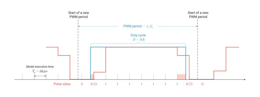
The generator outputs the pulse value using a modulation method based on a carrier frequency with natural sampling. If a transition occurs during the sampling period, the oscillator outputs a pulse value representing the ratio of time (the value from 0 before 1) inclusions to the sampling period. For example, with the sampling period indicated by the first blue arrow, the generator outputs the value 0.25. This means that the pulse was turned on after seconds, i.e. it was turned on during 25% of the time of the sampling period of the model. The offset is indicated by an area filled in red. Similarly, with the sampling period indicated by the second blue arrow, the generator outputs the value 0.75. This means that the pulse has turned on during 75% of the time of the sampling period of the model, i.e. switched to the off state after seconds after the previous sampling period.
Ports
Entrance
# Vref — reference voltage
+
vector | scalar
Details
The reference signal used to generate the output pulses is specified as a three-phase vector or a single-phase scalar. Connect this port to a single-phase sinusoidal signal if the unit is used to control a single-phase full-bridge converter, or to a three-phase sinusoidal signal if the PWM generator unit controls a three-phase bridge converter. For linear operation of this unit, the value of Vref must be in the range of −1 before +1.
Dependencies
To use this port, set the parameter Generator type one of the following values:
-
Full-bridge, single phase; -
Two-level, three-phase; -
Three-level, three-phase.
| Типы данных |
|
| Support for complex numbers |
None |
# D — fill factor
+
scalar
Details
The fill factor of the PWM generator. The value must be in the range of 0 before 1.
Dependencies
To use this port, set the parameter Generator type meaning Two-quadrant.
| Типы данных |
|
| Support for complex numbers |
None |
Output
# P — pulse signals
+
vector
Details
Output pulses returned as a vector.
| Типы данных |
|
| Support for complex numbers |
None |
Parameters
Main group
#
Generator type —
The PWM model
Two-quadrant | Full-bridge, single phase | Two-level, three-phase | Three-level, three-phase
Details
The type of controlled generator. The number of pulses generated by the unit is proportional to the number of controlled bridge arms.
Select a value Two-quadrant to control the self-switching devices of a two-quadrant converter. The fill factor of the generator is set via the input port D. Its value determines the percentage of the pulse period during which the pulse is on.
Select a value Full-bridge, single phase to control the self-switching devices of a single-phase full-bridge converter. In this case, four pulses are generated. Pulses 1 and 3 control the upper devices of the first and second arms, and pulses 2 and 4 control the lower ones.
Select a value Two-level, three-phase to control the self-switching devices of a three-phase bridge two-level converter. Pulses 1, 3 and 5 control the upper devices of the first, second and third arms. Pulses 2, 4 and 6 control the lower devices.
Select a value Three-level, three-phase to control the self-switching devices of a three-phase bridge three-level converter. Impulses (1, 2), (5, 6) and (9, 10) control the upper devices of the first, second and third arms. Impulses (3, 4), (7, 8) and (11, 12) control the lower devices of all three arms.
| Values |
|
| Default value |
|
| Program usage name |
|
| Evaluatable |
Yes |
# Carrier frequency, Hz — frequency of the triangular carrier signal
Details
The frequency of the triangular carrier signal, measured in Hz. The value of this parameter must be higher. 0.
| Default value |
|
| Program usage name |
|
| Evaluatable |
Yes |
# Carrier initial phase, deg — the initial phase of the carrier signal
Details
The initial phase of the carrier signal, measured in degrees. Meaning 90 degrees means that the initial position of the triangular carrier signal is set in the middle between its minimum and maximum values, and the slope is positive.
| Default value |
|
| Program usage name |
|
| Evaluatable |
Yes |
# Sample time, s — sampling period
Details
The sampling period of the block, measured in seconds. The value must be positive or greater. 0.
| Default value |
|
| Program usage name |
|
| Evaluatable |
Yes |