Simplified Synchronous Machine
A simplified synchronous machine with an EMF.
blockType: AcausalElectricPowerSystems.Electromechanical.Synchronous.SimplifiedMachine
|
Path in the library: |

Description
Block Simplified Synchronous Machine simulates a simplified synchronous machine with a voltage source that represents an electromotive force (EMF). You can specify the internal active resistance and inductance with parameters in relative units or in SI units.
Equivalent circuits of a simplified synchronous machine for the longitudinal axis, transverse axis, and zero sequence:
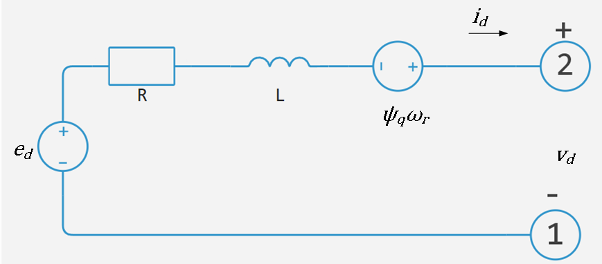
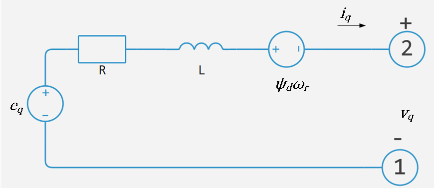
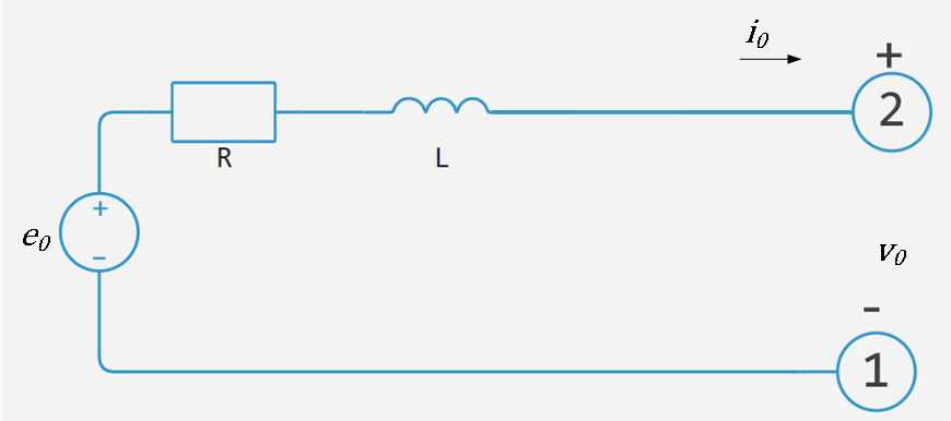
Flow coupling
Simplified equations of a synchronous machine are written with respect to a rotating frame of reference, which is defined as follows:
where
-
— electric angle;
-
— number of pairs of poles;
-
— the angle of the rotor (mechanical angle).
The Park—Gorev transformation maps the equations of a synchronous machine into a rotating frame of reference relative to an electric angle. It is written as follows:
The Park—Gorev transformation is written in relative units. The stress equations are as follows:
where
-
, and — stresses along the axes , and null sequences, defined as:
-
, and — internal voltage sources in relative units, defined as:
-
— the amplitude of the EMF in O.E.;
-
, and are defined as follows:
-
, and — stator voltages measured from port ~ to neutral n;
-
— base frequency in radians;
-
, and — flow coupling of axes , and the zero sequence;
-
— the speed of rotation of the rotor in oe.;
-
— active resistance of the stator;
-
, and — stator winding currents along the axis , and zero-sequence stator currents, defined as:
-
, and — stator currents flowing out of port ~.
The flow couplings of the stator are equal:
where — stator scattering inductance.
The power equation of a simplified synchronous machine in OE is as follows:
Variables
Use the parameter group Initial Targets to set the priority and initial target values for the block parameter variables before modeling. For more information, see Configuring physical blocks using target values.
Ports
Conserving
#
R
—
the rotor of the machine
rotational mechanics
Details
A mechanical rotary port corresponding to the machine’s rotor.
| Program usage name |
|
#
C
—
machine body
rotational mechanics
Details
A mechanical rotary port corresponding to the machine body.
| Program usage name |
|
#
~
—
stator winding
electricity
Details
Three-phase electrical port corresponding to the stator windings.
| Program usage name |
|
#
n
—
neutral
electricity
Details
The electrical port corresponding to the neutral point of the stator winding.
| Program usage name |
|
Output
#
o
—
current values of variables, O.E.
vector
Details
An output port that outputs the current values of the machine’s variables in OE; a vector of several elements. Vector elements:
-
EMF of phase A, .
-
EMF of phase b, .
-
EMF of phase C, .
-
The electromagnetic moment, .
-
Rotor speed, .
-
Stator voltage along the axis , .
-
Stator voltage along the axis , .
-
Voltage of the zero sequence of the stator, .
-
Current along the d axis of the stator, .
-
Current along the q axis of the stator, .
-
Stator zero sequence current, .
-
Electric angle of the rotor, .
To connect to this port, use the block Simplified Synchronous Machine Measurement.
| Data types |
|
| Complex numbers support |
No |
Input
#
E_si
—
amplitude of the internal generated voltage (phase-neutral)
vector
Details
The input port of the signal associated with the amplitude of the internal generated voltage (phase-neutral); a vector of three elements.
Dependencies
To use this port, set the parameter Parameterization unit meaning SI.
| Data types |
|
| Complex numbers support |
No |
#
E_pu
—
the amplitude of the internal generated voltage in relative voltage units
vector
Details
The port is associated with the amplitude in relative units of the internal generated voltage in the form of a vector.
Dependencies
To use this port, set the parameter Parameterization unit meaning Per unit.
| Data types |
|
| Complex numbers support |
No |
Parameters
Main
#
Rated apparent power —
Rated full power
W | uW | mW | kW | MW | GW | V*A | HP_DIN
Details
Rated power.
| Units |
|
| Default value |
|
| Program usage name |
|
| Evaluatable |
Yes |
#
Rated voltage —
RMS line voltage
V | uV | mV | kV | MV
Details
The nominal RMS line voltage.
| Units |
|
| Default value |
|
| Program usage name |
|
| Evaluatable |
Yes |
#
Rated electrical frequency —
Rated electrical frequency
Hz | kHz | MHz | GHz
Details
The rated electrical frequency at which the rated total power is indicated.
| Units |
|
| Default value |
|
| Program usage name |
|
| Evaluatable |
Yes |
# Number of pole pairs — number of pairs of poles
Details
The number of pairs of poles of the machine.
| Default value |
|
| Program usage name |
|
| Evaluatable |
Yes |
#
Parameterization unit —
units of measurement for block parameters
Per unit | SI
Details
Units of measurement for block parameters:
-
SI; -
Per unit.
| Values |
|
| Default value |
|
| Program usage name |
|
| Evaluatable |
No |
# Internal resistance, pu — internal active resistance
Details
Internal resistance.
Dependencies
To use this parameter, set for the parameter Parameterization unit meaning Per unit.
| Default value |
|
| Program usage name |
|
| Evaluatable |
Yes |
# Internal inductance, pu — internal inductance
Details
Internal inductance.
Dependencies
To use this parameter, set for the parameter Parameterization unit meaning Per unit.
| Default value |
|
| Program usage name |
|
| Evaluatable |
Yes |
#
Internal resistance —
internal active resistance
Ohm | mOhm | kOhm | MOhm | GOhm
Details
Internal active resistance.
Dependencies
To use this parameter, set for the parameter Parameterization unit meaning SI.
| Units |
|
| Default value |
|
| Program usage name |
|
| Evaluatable |
Yes |
#
Internal inductance —
internal inductance
H | nH | uH | mH
Details
Internal inductance.
Dependencies
To use this parameter, set for the parameter Parameterization unit meaning SI.
| Units |
|
| Default value |
|
| Program usage name |
|
| Evaluatable |
Yes |
Initial Conditions
#
Initialization option —
choosing initialization
Set targets for rotor angle and Park’s transform variables | Set real power, reactive power, terminal voltage, and terminal phase | Set targets for load flow variables
Details
The method of setting parameter and variable values at the beginning of the simulation:
-
Set real power, reactive power, terminal voltage, and terminal phase— nominal parameters are set independently of the connected network. -
Set targets for rotor angle and Park’s transform variables— priority and initial target values for block variables are set before simulation using settings Initial Targets.
Dependencies
If you set this parameter to:
-
Set targets for rotor angle and Park’s transform variables— the parameter settings section becomes visible Initial Targets. -
Set real power, reactive power, terminal voltage, and terminal phase— the parameter settings section becomes visible Initial Conditions.
| Values |
|
| Default value |
|
| Program usage name |
|
| Evaluatable |
No |
#
Source type —
description missing
Swing bus | PV bus | PQ bus
Details
description missing
| Values |
|
| Default value |
|
| Program usage name |
|
| Evaluatable |
No |
#
Terminal voltage magnitude —
the initial voltage amplitude at the terminals
V | uV | mV | kV | MV
Details
The initial voltage amplitude at the terminals.
Dependencies
To use this parameter, set for the parameter Initialization option meaning Set real power, reactive power, terminal voltage, and terminal phase.
| Units |
|
| Default value |
|
| Program usage name |
|
| Evaluatable |
Yes |
#
Terminal voltage angle —
the initial phase of terminal voltage
rad | deg | rev | mrad | arcsec | arcmin | gon
Details
The initial phase of the terminal voltage.
Dependencies
To use this parameter, set for the parameter Initialization option meaning Set real power, reactive power, terminal voltage, and terminal phase.
| Units |
|
| Default value |
|
| Program usage name |
|
| Evaluatable |
Yes |
#
Active power generated —
generated active power
W | uW | mW | kW | MW | GW | V*A | HP_DIN
Details
Generated active power.
Dependencies
To use this parameter, set for the parameter Initialization option meaning Set real power, reactive power, terminal voltage, and terminal phase.
| Units |
|
| Default value |
|
| Program usage name |
|
| Evaluatable |
Yes |
#
Reactive power generated —
generated reactive power
W | uW | mW | kW | MW | GW | V*A | HP_DIN
Details
Generated reactive power.
Dependencies
To use this parameter, set for the parameter Initialization option meaning Set real power, reactive power, terminal voltage, and terminal phase.
| Units |
|
| Default value |
|
| Program usage name |
|
| Evaluatable |
Yes |
Main
# Display Associated Initial Conditions — displaying the initial conditions
Details
Display the corresponding initial conditions in the diagnostic window of the model.
| Default value |
|
| Program usage name |
|
| Evaluatable |
No |