Double-Acting Actuator (G)
Two-way linear actuator in the gas network.
blockType: EngeeFluids.Gas.Actuators.TranslationalDoubleActing
|
Path in the library: |

Description
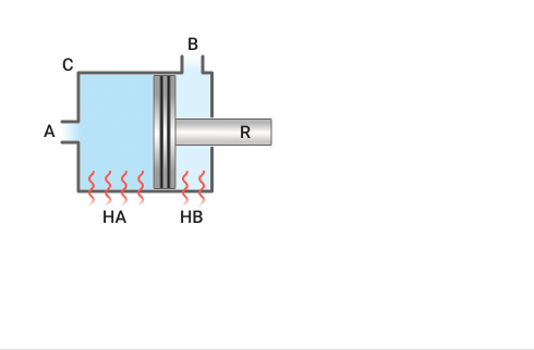
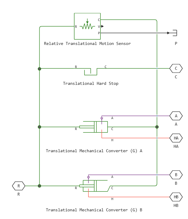
Block Double-Acting Actuator (G) It simulates a drive that converts the pressure difference between two chambers into a piston movement. The movement of the piston is controlled by the pressure drop on both sides of the plate separating the chambers of the block. The stroke limits of the piston are modeled by one of the rigid stop models.
The figure shows the main components of the drive. Ports A and B are gas inputs. Port C is associated with the drive housing, port R is associated with the piston, and it returns the speed of the piston. The position of the piston is calculated inside the system and transmitted to port p.
Ports HA and HB represent the thermal interfaces between each gas chamber and the surrounding environment. The moving piston is adiabatic.
Moving
The movement of the piston is determined by the displacement of port R relative to port C. Parameter Value Mechanical orientation determines the direction of displacement of the piston. The movement of the piston is neutral (equal to 0), when the volume of the camera A is Dead volume in chamber A.
The direction of movement of the piston depends on the parameter Mechanical orientation. If the value is set to Pressure at A causes positive displacement of R relative to C, the displacement of the piston will be positive with respect to the drive housing when the gauge pressure at port A is positive. The direction of movement is reversed if the value is set to Pressure at A causes negative displacement of R relative to C.
The hard limiter model
A set of rigid stops limits the range of motion of the piston. This block uses the implementation of the block Translational Hard Stop in which rigid stops are considered as spring-damping systems. The spring stiffness coefficient determines the restoring component of the contact force of the rigid stop, and the damping coefficient determines the scattering component.
Rigid stops are located at the distal ends of the piston stroke. If the mechanical orientation is positive, then the lower rigid stop is in position , and the upper rigid stop is in position . If the mechanical orientation is negative, then the lower rigid stop is in position , and the upper rigid stop is in position .
Ports
Conserving
#
A
—
inlet for gas flow into the chamber A
gas
Details
The port corresponding to the gas inlet to the chamber A.
| Program usage name |
|
#
B
—
inlet for gas flow into the chamber B
gas
Details
The port corresponding to the gas inlet to the chamber B.
| Program usage name |
|
#
R
—
drive piston
translational mechanics
Details
A mechanical translational port corresponding to the drive piston.
| Program usage name |
|
#
C
—
drive housing
translational mechanics
Details
Mechanical translational port corresponding to the drive housing.
| Program usage name |
|
#
HA
—
heat associated with the camera A
heat
Details
Thermal non-directional port connected to camera A.
| Program usage name |
|
#
HB
—
heat associated with the camera B
heat
Details
Thermal non-directional port connected to the camera B.
| Program usage name |
|
Output
#
p
—
piston position
scalar
Details
The position of the piston in m.
| Data types |
|
| Complex numbers support |
I don’t |
Parameters
Actuator
# Same fluid on both sides — is the same fluid simulated in both chambers of the unit
Details
Whether the same fluid is simulated on both sides of the block. If the option is checked, then the properties of the liquid are distributed through the block. If unchecked, the chambers of the unit are connected to isolated networks of liquids with different properties.
| Default value |
|
| Program usage name |
|
| Evaluatable |
No |
#
Mechanical orientation —
the direction of movement of the piston
Pressure at A causes positive displacement of R relative to C | Pressure at A causes negative displacement of R relative to C
Details
Determines the direction of movement of the piston. Options to choose from:
-
Pressure at A causes positive displacement of R relative to C— the movement of the piston is positive if the volume of gas in port A increases. This corresponds to the movement of the rod out of the cylinder. -
Pressure at A causes negative displacement of R relative to C— piston displacement is negative if the volume of gas in port A increases. This corresponds to the movement of the rod inside the cylinder.
| Values |
|
| Default value |
|
| Program usage name |
|
| Evaluatable |
No |
#
Piston cross-sectional area in chamber A —
the cross-sectional area of the piston rod of the chamber A
m^2 | um^2 | mm^2 | cm^2 | km^2 | in^2 | ft^2 | yd^2 | mi^2 | ha | ac
Details
The cross-sectional area of the piston rod on the side of the chamber A.
| Units |
|
| Default value |
|
| Program usage name |
|
| Evaluatable |
Yes |
#
Piston cross-sectional area in chamber B —
the cross-sectional area of the piston rod of the chamber B
m^2 | um^2 | mm^2 | cm^2 | km^2 | in^2 | ft^2 | yd^2 | mi^2 | ha | ac
Details
The cross-sectional area of the piston rod on the side of the chamber B.
| Units |
|
| Default value |
|
| Program usage name |
|
| Evaluatable |
Yes |
#
Piston stroke —
stroke of the piston
m | um | mm | cm | km | in | ft | yd | mi | nmi
Details
The maximum possible displacement of the piston.
| Units |
|
| Default value |
|
| Program usage name |
|
| Evaluatable |
Yes |
#
Dead volume in chamber A —
the volume of gas in the chamber A, at which the movement of the piston is 0
m^3 | um^3 | mm^3 | cm^3 | km^3 | ml | l | gal | igal | in^3 | ft^3 | yd^3 | mi^3
Details
The volume of gas in the chamber A at the value of the piston displacement 0. This volume of gas corresponds to the position of the piston, at which it is located at the top in relation to the end cap of the actuator.
| Units |
|
| Default value |
|
| Program usage name |
|
| Evaluatable |
Yes |
#
Dead volume in chamber B —
the volume of gas in the chamber B at which the piston movement is 0
m^3 | um^3 | mm^3 | cm^3 | km^3 | ml | l | gal | igal | in^3 | ft^3 | yd^3 | mi^3
Details
The volume of gas in the chamber B at the value of the piston displacement 0. This volume of gas corresponds to the position of the piston, at which it is located at the top in relation to the end cap of the actuator.
| Units |
|
| Default value |
|
| Program usage name |
|
| Evaluatable |
Yes |
#
Cross-sectional area at port A —
port cross-sectional area A
m^2 | um^2 | mm^2 | cm^2 | km^2 | in^2 | ft^2 | yd^2 | mi^2 | ha | ac
Details
The cross-sectional area at the entrance.
| Units |
|
| Default value |
|
| Program usage name |
|
| Evaluatable |
Yes |
#
Cross-sectional area at port B —
port cross-sectional area B
m^2 | um^2 | mm^2 | cm^2 | km^2 | in^2 | ft^2 | yd^2 | mi^2 | ha | ac
Details
The cross-sectional area at the outlet.
| Units |
|
| Default value |
|
| Program usage name |
|
| Evaluatable |
Yes |
#
Environment pressure specification —
the method of setting the ambient pressure
Atmospheric pressure | Specified pressure
Details
The method of setting the ambient pressure. Option Atmospheric pressure sets the ambient pressure equal to 0.101325 MPa.
| Values |
|
| Default value |
|
| Program usage name |
|
| Evaluatable |
No |
#
Environment pressure —
ambient pressure
Pa | uPa | hPa | kPa | MPa | GPa | kgf/m^2 | kgf/cm^2 | kgf/mm^2 | mbar | bar | kbar | atm | ksi | psi | mmHg | inHg
Details
User-defined ambient pressure.
Dependencies
To use this parameter, set for the parameter Environment pressure specification meaning Specified pressure.
| Units |
|
| Default value |
|
| Program usage name |
|
| Evaluatable |
Yes |
Hard Stop
#
Hard-stop model —
choosing a rigid stop model
Stiffness and damping applied smoothly through transition region, damped rebound | Full stiffness and damping applied at bounds, undamped rebound | Full stiffness and damping applied at bounds, damped rebound | Based on coefficient of restitution
Details
Selecting a model for the force acting on the piston when it is in extreme positions. For more information, see the block Translational Hard Stop.
| Values |
|
| Default value |
|
| Program usage name |
|
| Evaluatable |
No |
#
Hard-stop stiffness coefficient —
stiffness coefficient
N/m | mN/m | kN/m | MN/m | GN/m | kgf/m | lbf/ft | lbf/in
Details
The coefficient of piston stiffness.
| Units |
|
| Default value |
|
| Program usage name |
|
| Evaluatable |
Yes |
#
Hard-stop damping coefficient —
damping coefficient
N*s/m | kgf*s/m | lbf*s/ft | lbf*s/in
Details
Piston damping coefficient.
| Units |
|
| Default value |
|
| Program usage name |
|
| Evaluatable |
Yes |
#
Transition region —
the range of action of the rigid stop model
m | um | mm | cm | km | in | ft | yd | mi | nmi
Details
The area of operation of the rigid stop. Outside of this range for the extreme positions of the piston Hard-stop model it is not applied, and the additional force from the stop side does not act on the piston.
Dependencies
To use this parameter, set for the parameter Hard-stop model meaning Stiffness and damping applied smoothly through transition region, damped rebound.
| Units |
|
| Default value |
|
| Program usage name |
|
| Evaluatable |
Yes |
# Coefficient of restitution — the ratio of the final and initial relative velocity between the rod and the stop after a collision
Details
The ratio of the final and initial relative velocity between the rod and the stop after the rod rebounds.
Dependencies
To use this parameter, set for the parameter Hard-stop model meaning Based on coefficient of restitution.
| Default value |
|
| Program usage name |
|
| Evaluatable |
Yes |
#
Static contact speed threshold —
threshold value of the relative velocity between the rod and the stop before the collision
m/s | mm/s | cm/s | km/s | m/hr | km/hr | in/s | ft/s | mi/s | ft/min | mi/hr | kn
Details
The threshold value of the relative velocity between the rod and the stop before the collision. If the rod hits the housing at a speed lower than the value of this parameter, they remain in contact. Otherwise, the rod bounces off. To avoid simulating static contact between the rod and the housing, set this parameter to 0.
Dependencies
To use this parameter, set for the parameter Hard-stop model meaning Based on coefficient of restitution.
| Units |
|
| Default value |
|
| Program usage name |
|
| Evaluatable |
Yes |
#
Static contact release force threshold —
the threshold value of the force required to transition from the contact state to the free state
N | nN | uN | mN | kN | MN | GN | dyn | lbf | kgf
Details
The minimum force required to remove the rod from the static contact state.
Dependencies
To use this parameter, set for the parameter Hard-stop model meaning Based on coefficient of restitution.
| Units |
|
| Default value |
|
| Program usage name |
|
| Evaluatable |
Yes |
Initial Conditions
#
Initial piston displacement from chamber A cap —
the initial position of the piston relative to the chamber cover A
m | um | mm | cm | km | in | ft | yd | mi | nmi
Details
The position of the piston relative to the chamber cover A at the beginning of the simulation.
| Units |
|
| Default value |
|
| Program usage name |
|
| Evaluatable |
Yes |
#
Initial gas pressure in chamber A —
initial gas pressure in the chamber A
Pa | uPa | hPa | kPa | MPa | GPa | kgf/m^2 | kgf/cm^2 | kgf/mm^2 | mbar | bar | kbar | atm | ksi | psi | mmHg | inHg
Details
The initial gas pressure in the chamber is A.
| Units |
|
| Default value |
|
| Program usage name |
|
| Evaluatable |
Yes |
#
Initial gas pressure in chamber B —
initial gas pressure in the chamber B
Pa | uPa | hPa | kPa | MPa | GPa | kgf/m^2 | kgf/cm^2 | kgf/mm^2 | mbar | bar | kbar | atm | ksi | psi | mmHg | inHg
Details
The initial gas pressure in the chamber is B.
| Units |
|
| Default value |
|
| Program usage name |
|
| Evaluatable |
Yes |
#
Initial gas temperature in chamber A —
the initial temperature of the gas in the chamber A
K | degC | degF | degR | deltaK | deltadegC | deltadegF | deltadegR
Details
The initial temperature of the gas in the chamber is A.
| Units |
|
| Default value |
|
| Program usage name |
|
| Evaluatable |
Yes |
#
Initial gas temperature in chamber B —
initial temperature of the gas in the chamber B
K | degC | degF | degR | deltaK | deltadegC | deltadegF | deltadegR
Details
The initial temperature of the gas in the chamber is B.
| Units |
|
| Default value |
|
| Program usage name |
|
| Evaluatable |
Yes |