Smoothly Curved Elbow (G)
Pipe rotation (knee) in the gas network.
blockType: EngeeFluids.Gas.Fittings.Elbow
|
Sharp-Edged Elbow (G) Path in the library: |
|
Smoothly Curved Elbow (G) Path in the library: |


Description
The Elbow (G) block simulates the flow at the turn of a pipeline in a gas network. In this case, pressure losses are calculated when the pipe is rotated, but the influence of viscous friction is not taken into account.
Two types of knee are available: Smoothly curved (smoothly curved) and Sharp-edged (Miter) (acute-angled or oblique). For modeling a smooth pipe with a bend 90°, which takes into account losses due to friction, you can also use the block Pipe Bend (G).
Loss coefficients
If for the parameter Elbow type the value is set Smoothly curved The block calculates the loss factor as follows:
where — the angle correction coefficient calculated by the Keller block [2] as
where — parameter value Bend angle in degrees. The block determines the coefficient of friction as a value for pure commercial steel. The block then interpolates the values from the tabular data depending on the inner diameter of the elbow for [1]. The table below shows data on friction in a pipe for pure commercial steel during flow in a zone of complete turbulence.
| 1 | 1.5 | 2 | 3 | 4 | 6 | 8 | 10 | 12 | 14 | 16 | 20 | 24 | |
|---|---|---|---|---|---|---|---|---|---|---|---|---|---|
|
|
|
|
|
|
|
|
|
|
|
|
|
|
The values given are valid for diameters up to 600 The coefficient of friction for large diameters or for wall roughness outside this range is calculated by extrapolating the nearest neighbors.
If for the parameter Elbow type the value is set Sharp-edged (Miter), the block calculates the loss coefficient for the bending angle according to [1] as follows:
| , ° | 0 | 15 | 30 | 45 | 60 | 75 | 90 |
|---|---|---|---|---|---|---|---|
|
|
|
|
|
|
|
|
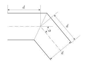
Conservation of mass
The mass conservation equation for a section of pipe has the form:
The mass flow through the knee is
where
-
— flow area;
-
— average gas density;
-
— pressure drop in the pipe section.
Critical pressure drop It is the threshold value for the transition between laminar and turbulent flows.:
where
-
— port pressure A;
-
— port pressure B;
-
— parameter value Laminar flow pressure ratio.
Ports
Conserving
#
B
—
input or output port
gas
Details
A non-directional port connected to the inlet or outlet port of a pipe section.
| Program usage name |
|
#
A
—
input or output port
gas
Details
A non-directional port connected to the inlet or outlet port of a pipe section.
| Program usage name |
|
Parameters
Main
#
Elbow type —
bending geometry
Smoothly curved | Sharp-edged (Miter)
Details
The geometry of the bend of the pipe section. If the value is set to Sharp-edged (Miter) The block makes a drastic change in the flow direction, for example, at the pipe junction, and flow losses are modeled by a separate set of empirical data obtained on pipe sections with gradual rotation.
| Values |
|
| Default value |
|
| Program usage name |
|
| Evaluatable |
No |
#
Elbow angle —
pipe rotation angle
rad | deg | rev | mrad | arcsec | arcmin | gon
Details
The angle of rotation of the pipe.
| Units |
|
| Default value |
|
| Program usage name |
|
| Evaluatable |
Yes |
#
Elbow internal diameter —
inner diameter of the pipe
m | um | mm | cm | km | in | ft | yd | mi | nmi
Details
The inner diameter of the pipe section.
| Units |
|
| Default value |
|
| Program usage name |
|
| Evaluatable |
Yes |
# Laminar flow pressure ratio — the pressure ratio at which the flow transitions between laminar and turbulent modes
Details
The pressure ratio at which the gas flow transitions between laminar and turbulent modes.
| Default value |
|
| Program usage name |
|
| Evaluatable |
Yes |