Pipe Bend (G)
Bending of a pipe in a gas network.
blockType: EngeeFluids.Gas.Pipes.Bend
|
Path in the library: |

Description
In the block Pipe Bend (G) The gas dynamics of a curved pipe in a gas network is modeled. The characteristics of the pipe can be determined so that calculations of losses due to friction and curvature of the pipe can be performed.
Pipe curvature loss coefficient
The coefficient of local resistance (pressure loss) of the curved section of the channel includes a correction factor for the angle of rotation of the channel and the channel bending coefficient :
In the coefficient block calculated as follows:
where — the angle of rotation of the channel in degrees, the value of the parameter Bend angle.
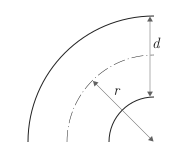
Ratio It is calculated on the basis of experimental data — a table of the dependence of the desired coefficient on the ratio of the bending radius. to the pipe diameter for channel rotation angles 90° according to [1]:
| 1 | 1.5 | 2 | 3 | 4 | 6 | 8 | 10 | 12 | 14 | 16 | 20 | 24 | |
|---|---|---|---|---|---|---|---|---|---|---|---|---|---|
|
|
|
|
|
|
|
|
|
|
|
|
|
|
Coefficient of friction It is interpolated based on tabular data taken for technical steels, depending on the pipe diameter [1]. The table below shows the data for the coefficient of friction of a gas flow with developed turbulence in pipes made of industrial steels.
| Nominal size, mm | 5 | 10 | 15 | 20 | 25 | 32 | 40 | 50 | 72.5 | 100 | 125 | 150 | 225 | 350 | 609.5 |
|---|---|---|---|---|---|---|---|---|---|---|---|---|---|---|---|
Coefficient of friction |
|
|
|
|
|
|
|
|
|
|
|
|
|
|
|
The correction factor of the channel rotation angle is valid for curved pipes (channels) in which the ratio of the bending radius to the pipe diameter ranges from 1 before 24. Outside of this range, nearest neighbor extrapolation is used.
Friction losses in the laminar flow regime
The pressure loss expressions are the same for the flows in ports A and B.
In the case of a laminar flow regime in a pipe bend, or when the Reynolds number is below the critical value , the pressure loss at the bend of the pipe is determined as follows:
where
-
— dynamic viscosity of the liquid;
-
is the constant of the coefficient of friction (Darcy coefficient), which is equal to
64for laminar flow mode; -
— the density of the liquid inside the pipe;
-
— pipe diameter;
-
— the length of the curved section of the pipe (pipe bend), defined as the product of the parameters Bend radius and Bend angle: ;
-
— the cross-sectional area of the pipe, ;
-
— mass flow rate at the appropriate port.
Friction losses in the turbulent flow regime
For flows with developed turbulence, or if the Reynolds number exceeds the critical value , the pressure loss in the pipe bend is determined as follows:
where — Darcy’s coefficient of friction. It is approximated by the empirical Haaland equation and is determined by the absolute roughness of the inner surface (the value of the parameter Internal surface absolute roughness). The pressure drop is taken in half of the pipe section, between port A and the inner node, as well as between the inner node and port B.
Pressure drop
When calculating the pressure loss at the bend of the pipe, the pressure inside the curved pipe is also taken into account. :
Conservation of mass
The law of conservation of mass relates the mass flow rate to the dynamics of pressure and temperature of the internal unit representing the volume of gas:
where:
-
is the partial derivative of the mass of the gas volume in terms of pressure at constant temperature and volume;
-
is the partial derivative of the mass of the gas volume with respect to temperature at constant pressure and volume;
-
— gas volume pressure;
-
— the temperature of the gas volume;
-
— time;
-
and — massive expenses on ports A and B respectively. The flow rate in the port is positive if gas enters the unit through this port.
Energy conservation
The law of conservation of energy relates the flow of energy and heat consumption to the dynamics of pressure and temperature of the internal unit representing the volume of gas:
where
-
is the partial derivative of the internal energy of the gas volume in terms of pressure at constant temperature and volume;
-
is the partial derivative of the internal energy of the gas volume with respect to temperature at constant pressure and volume;
-
and — energy flows at ports A and B respectively.
Variables
Use the Initial targets parameter group to set the priority and initial target values for the block parameter variables before modeling. For more information, see Configuring physical blocks using target values.
Parameters
Main
#
Bend radius —
bending radius
m | um | mm | cm | km | in | ft | yd | mi | nmi
Details
The radius of the circle formed by the bend of the pipe.
| Units |
|
| Default value |
|
| Program usage name |
|
| Evaluatable |
Yes |
#
Bend angle —
bending angle
rad | deg | rev | mrad | arcsec | arcmin | gon
Details
The angle of rotation of the channel or the bend of the pipe.
| Units |
|
| Default value |
|
| Program usage name |
|
| Evaluatable |
Yes |
#
Internal surface absolute roughness —
the roughness of the walls of a curved pipe
m | um | mm | cm | km | in | ft | yd | mi | nmi
Details
The absolute roughness of the curved pipe walls. The parameter is used to determine the Darcy coefficient, which affects the pressure loss in the pipe.
| Units |
|
| Default value |
|
| Program usage name |
|
| Evaluatable |
Yes |
#
Pipe diameter —
pipe diameter
m | um | mm | cm | km | in | ft | yd | mi | nmi
Details
Pipe diameter.
| Units |
|
| Default value |
|
| Program usage name |
|
| Evaluatable |
Yes |