Heat Exchanger (G-TL)
Heat exchanger for systems with gas and heat-conducting liquid flows
blockType: EngeeFluids.HeatExchangers.EffectivenessNTU.GasThermalLiquid
|
Path in the library: |

Description
Block Heat Exchanger (G-TL) simulates additional cooling and heating of heat carriers in short-term thermal contact through a thin conductive wall. The wall of the heat exchanger has thermal inertia capable of storing heat, which introduces a time delay in energy transfer proportional to its thermal mass. The heat carriers are homogeneous in phase state: on the one hand, pure gas, on the other, pure liquid. The phase transition in the process is excluded, which determines exclusively the contact heat exchange (without latent heat).
Contact heat exchangers are widely used in engineering. Fuel heaters, which in some jet engines prevent ice from settling in fuel lines and clogging fuel strainers, work by supplying hot air coming out of the compressor to the fuel lines. Oil radiators, which in some motorcycles protect the lubricating oil from overheating, work in a similar way by pumping air into the oil lines at ambient temperature. Air is a gas stream, and fuel or oil is a flow of heat—conducting liquid.

The heat transfer model
The block’s heat transfer model is based on the "efficiency-number of heat transfer units" (E-NTU) method. In steady-state mode, heat exchange is carried out with an efficiency equal to only a fraction of the ideal value, which is achievable in the absence of thermal resistance and constant temperatures at the flow inlet.:
where
-
— actual heat flow;
-
— perfect heat flow;
-
— the fraction of the ideal heat flow actually observed in a real heat exchanger in which there are losses. This value determines the efficiency of the heat exchanger and is a function of the number of transfer units, or .
Dimensionless parameter It reflects the relative efficiency of inter-flow heat exchange in comparison with the ability of streams to accumulate the transferred heat.:
where
-
— coefficient of thermal conductivity between the streams;
-
— the minimum value of the flow heat capacity related to the flow with the least ability to absorb heat.
The flow heat capacity depends on the specific heat capacity of the coolant ( ) and from its mass flow through the heat exchanger ( ):
Efficiency also depends on the relative position of the streams, the number of strokes between them, and the flow mixing conditions. Each coolant flow pattern uses its own efficiency expression. The list of such expressions is given in the block E-NTU Heat Transfer.
Flow diagram of heat carriers
Parameter Flow arrangement defines the mutual direction of flows: direct flow, countercurrent, across each other (transverse), as well as the "pipe in a casing" design, in which one flow passes inside the pipes and the other outside, in the casing. The figure below illustrates this flow pattern. The flow in the pipes can make either one stroke through the casing (Fig. on the right) or several strokes (Fig. on the left) for greater heat exchange efficiency.

Alternative flow patterns of heat carriers can be set by general parameterization with tabular efficiency data, which does not require a detailed specification of the heat exchanger. Such data should reflect the flow pattern of the heat carriers, the degree of their mixing, and the number of passages through the casing or pipe.
Mixing conditions
Parameter Cross flow type allows you to set the mixing pattern: one of the streams is mixed, both or none. Mixing involves the transverse movement of the coolant in channels devoid of internal barriers (guides, partitions, ribs or walls). It helps to equalize the temperature gradients in the cross-section. In unmixed streams, as shown in the figure below on the right, the temperature changes only along the flow direction, in mixed streams (Fig. on the left) — both longitudinally and transversely.

The difference between mixed and unmixed flows is taken into account only in the flow patterns of heat carriers with transverse flows, where a longitudinal change in the temperature of one coolant induces transverse temperature gradients in the other. In the schemes of direct-flow/countercurrent movement of heat carriers, only longitudinal changes in the temperatures of the heat carriers occur and mixing practically does not affect heat transfer, therefore it is not taken into account.
Efficiency curves
Shell-and-tube multi-pass heat exchangers are the most effective (iv.b-e in the figure for 2, 3 and 4 passes). Among single-stroke heat exchangers, countercurrent heat exchangers (ii) are the most efficient, while direct-flow heat exchangers (i) are the least efficient.
Cross-flow heat exchangers occupy an intermediate position in terms of efficiency and their efficiency depends on the degree of mixing. The highest is achieved when there is no mixing in both streams (iii.a), the lowest is achieved when both are mixed (iii.b). Mixing only the stream with the lowest flow heat capacity (iii.c) reduces efficiency to a greater extent than mixing the stream with the highest flow heat capacity (iii.d).

Thermal resistance
Total thermal resistance, , is the sum of local resistances in the direction of heat transfer. These include: convection on the wall surface and thermal conduction through the wall and contaminated layers in the presence of deposits. The formula below is used to calculate the total resistance in the direction from a gas to a thermally conductive liquid.:
where
-
and — coefficients of convective heat transfer for gas and heat-conducting liquid, respectively;
-
and — the coefficient of deposits on the wall from the side for gas and heat-conducting liquid, respectively;
-
and — the surface areas of heat transfer from the side for gas and heat-conducting liquid , respectively;
-
— thermal resistance of the wall.

The thermal resistance of the wall and the deposition coefficients are constants set in the block parameters. At the same time, heat transfer coefficients are complex functions that depend on the properties of the coolant, flow geometry, and wall friction. They are calculated based on empirical correlations between the Reynolds, Nusselt, and Prandtl numbers. The choice of a specific correlation depends on the flow pattern of the heat carriers and the mixing conditions, and is described in detail in the block E-NTU Heat Transfer, which the block model is based on.
Wall heat capacity
The wall is not only a thermal resistance, it also has a heat capacity and is able to accumulate heat within its mass. The accumulation of heat slows down the transition between steady-state modes, so that a thermal disturbance on one side does not immediately affect the other. The delay persists until the heat flows from both sides are balanced. This delay depends on the heat capacity of the wall:
where
-
— specific heat capacity of the wall;
-
— the mass of the wall.
The product of the specific heat capacity and the mass of the wall provides the energy needed to increase the temperature of the wall by one degree. Use the block parameter Wall thermal mass to set this piece. The parameter is used when the checkbox is checked. Wall thermal dynamics.
In low-pressure systems, the heat capacity can often be neglected. The low pressure provides the thin wall with such a fast transient reaction that it is almost instantaneous on the heat transfer time scale. The same cannot be said about the high-pressure systems common in the production of ammonia using the Haber method, where the pressure can exceed 200 atmospheres. To withstand high pressure, the walls are often made thicker, and since their heat capacity is greater, the transition process is slower.
Uncheck the box Wall thermal dynamics to ignore the thermal inertia of the wall, and speed up the simulation speed by reducing calculations. Check the box Wall thermal dynamics to take into account the thermal inertia of the wall where it has a noticeable effect. If necessary, experiment with the settings to determine if the heat capacity of the wall needs to be taken into account. If the simulation results differ significantly, and if the simulation speed is not a significant factor, then check the box. Wall thermal dynamics.
If the heat capacity of the wall is taken into account, then only half of it is considered. One half is located on the gas side, and the other half is on the side of the heat—conducting liquid. The gas side is designated as side 1, and the side with a heat—conducting liquid is designated as side 2. This designation is used in heat transfer calculations. The heat capacity is evenly distributed between these halves:
Energy is stored in the wall. In the simple case, when half of the wall is in a stable state, the heat received from the coolant is equal to the heat lost by the other half of the wall. The heat flow is determined by the E-NTU method for a wall without a heat capacity (see block E-NTU Heat Transfer). The flow rate is positive for heat flows directed from side 1 of the heat exchanger to side 2:
In the transition state, the wall is in the process of heat accumulation or loss, and the heat received by one half is no longer equal to the heat lost by the other half. The difference in heat consumption varies over time in proportion to the rate at which the wall accumulates or loses heat. For side 1 of the heat exchanger:
where — the rate of temperature change in half of the wall. The product of this velocity by the heat capacity of half of the wall gives the rate of heat accumulation in it. This rate is positive when the temperature rises, and negative when it decreases. The closer the velocity is to zero, the closer the wall is to steady state. For side 2 of the heat exchanger:
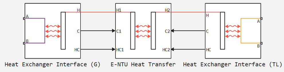
Block structure
A block is a composite component built from simpler blocks. The gas flow from one side of the heat exchanger is modeled using the block Heat Exchanger Interface (G). The flow of heat-conducting liquid from the other side of the heat exchanger is modeled using the block Heat Exchanger Interface (TL). Heat exchange through the wall between the flows is modeled using the block E-NTU Heat Transfer.
Ports
Conserving
#
B1
—
gas inlet or outlet
gas
Details
Inlet or outlet port for gas on the corresponding side of the heat exchanger.
| Program usage name |
|
#
A1
—
gas inlet or outlet
gas
Details
Inlet or outlet port for gas on the corresponding side of the heat exchanger.
| Program usage name |
|
#
B2
—
thermal liquid inlet or outlet
thermal liquid
Details
Inlet or outlet port for thermal liquid on the corresponding side of the heat exchanger.
| Program usage name |
|
#
A2
—
thermal liquid inlet or outlet
thermal liquid
Details
Inlet or outlet port for thermal liquid on the corresponding side of the heat exchanger.
| Program usage name |
|
Parameters
Gas 1
#
Gas-wall heat transfer coefficient —
heat transfer coefficient by convection between gas and wall
W/(m^2*K) | Btu_IT/(hr*ft^2*deltadegR)
Details
Heat transfer coefficient for convection between gas and wall. Resistance caused by deposits is accounted for separately in the parameters Fouling factor.
Dependencies
To use this parameter, set the Heat transfer coefficient model parameters to . Constant heat transfer coefficient.
| Units |
|
| Default value |
|
| Program usage name |
|
| Evaluatable |
Yes |
#
Length of flow path from inlet to outlet —
distance travelled from port to port
m | um | mm | cm | km | in | ft | yd | mi | nmi
Details
The total distance the flow must travel between ports. In multi-pass shell-and-tube heat exchangers, the total distance is the sum of all the passes through the shell. In tube bundles, corrugated plates and other ducts where the flow is divided into parallel branches, it is the distance travelled per branch. The longer the flow path, the greater the basic pressure loss due to viscous friction against the walls.
Dependencies
To use this parameter, set the parameters Pressure loss model to the value of Correlation for flow inside tubes or Tabulated data - Darcy friction factor vs. Reynolds number.
| Units |
|
| Default value |
|
| Program usage name |
|
| Evaluatable |
Yes |
#
Fouling factor —
thermal resistance due to deposits
K*m^2/W | deltadegR*ft^2*hr/Btu_IT
Details
Thermal resistance due to deposits that form over time on exposed wall surfaces. Deposits, because they create a new solid layer between the heat transfer medium and the wall through which heat must pass, add additional thermal resistance to the heat transfer path. The deposits grow slowly and the resistance caused by them is accordingly assumed to be constant during the simulation.
| Units |
|
| Default value |
|
| Program usage name |
|
| Evaluatable |
Yes |
#
Internal surface absolute roughness —
average height of roughnesses on the wall surface that result in viscous friction losses
m | um | mm | cm | km | in | ft | yd | mi | nmi
Details
The average height of the roughnesses on the wall surface that result in viscous friction losses. The greater the average height, the rougher the wall and the greater the pressure loss due to viscous friction. The surface roughness value is used to derive the Darcy friction coefficient from the Haaland relationship.
Dependencies
To use this parameter, set the parameter Pressure loss model to the value of Correlation for flow inside tubes.
| Units |
|
| Default value |
|
| Program usage name |
|
| Evaluatable |
Yes |
# Darcy friction factor vector — Darcy friction coefficient at each reference point in the Reynolds number look-up table
Details
Darcy friction coefficient at each reference point in the Reynolds number lookup table. The block interpolates and extrapolates the table values to determine the Darcy friction coefficient at any Reynolds number. Interpolation is performed using a linear function, and extrapolation is performed to the nearest value.
The values of the Darcy friction coefficient shall not be negative and shall line up from left to right in ascending order of the corresponding Reynolds numbers. The dimensionality of this vector should correspond to the dimensionality of the vector Reynolds number vector for Darcy friction factor for the calculation of tabulated reference points.
Dependencies
To use this parameter, set the parameter Pressure loss model to Tabulated data - Darcy friction factor vs. Reynolds number.
| Default value |
|
| Program usage name |
|
| Evaluatable |
Yes |
#
Minimum gas-wall heat transfer coefficient —
lower limit for the gas heat transfer coefficient
W/(m^2*K) | Btu_IT/(hr*ft^2*deltadegR)
Details
Lower limit for the heat transfer coefficient between gas and wall. If the calculation gives a lower heat transfer coefficient, the value Minimum gas-wall heat transfer coefficient replaces the calculated value.
| Units |
|
| Default value |
|
| Program usage name |
|
| Evaluatable |
Yes |
# Reynolds number vector for Colburn factor — Reynolds number at each reference point of the Colburn factor look-up table
Details
Reynolds number at each reference point of the Colburn factor lookup table. The block performs inter- and extrapolation of the table values to determine the Colburn factor at any Reynolds number. Interpolation is performed using a linear function, and extrapolation is performed to the nearest value.
The values of Reynolds numbers must be greater than zero and monotonically increasing from left to right. They can cover laminar, transient and turbulent regimes. The dimensionality of this vector should correspond to the dimensionality of the vector Colburn factor vector for the calculation of tabulated reference points.
Dependencies
To use this parameter, set the Heat transfer coefficient model parameters to Tabulated data - Colburn factor vs. Reynolds number.
| Default value |
|
| Program usage name |
|
| Evaluatable |
Yes |
# Nusselt number for laminar flow heat transfer — constant value of Nusselt number for laminar flow
Details
Constant value of Nusselt number for laminar flows. The Nusselt number is required to calculate the heat transfer coefficient between the heat transfer medium and the wall. The value by default corresponds to a cylindrical pipe.
Dependencies
To use this parameter, set the Heat transfer coefficient model parameters to Correlation for flow inside tubes.
| Default value |
|
| Program usage name |
|
| Evaluatable |
Yes |
#
Hydraulic diameter for pressure loss —
hydraulic diameter of the channel at its narrowest point
m | um | mm | cm | km | in | ft | yd | mi | nmi
Details
The effective internal diameter of the channel at the cross-section with the smallest area. For non-circular channels, the hydraulic diameter is the equivalent diameter of a circle with an area equal to the area of the existing channel. Its value is equal to the ratio of the minimum cross-sectional area of the channel to one quarter of its total perimeter.
If the channel is given by a set of channels, pipes, slots or grooves, the total perimeter is equal to the sum of the perimeters of all elements. If the channel is a circular pipe, its hydraulic diameter is equal to its actual diameter.
| Units |
|
| Default value |
|
| Program usage name |
|
| Evaluatable |
Yes |
# Nusselt number table, Nu(Re,Pr) — Nusselt number at each reference point of the Reynolds-Prandtl number search table
Details
Nusselt number at each reference point of the Reynolds-Prandtl number search table. The block interpolates and extrapolates the table values to determine the Nusselt number at any pair of Reynolds-Prandtl numbers. Interpolation is performed using a linear function, and extrapolation is performed to the nearest value. By determining the Nusselt number, the table provides the data for the calculation from which the heat transfer coefficient between the fluid and the wall is determined.
The Nusselt number must be greater than zero. Each value should be arranged from top to bottom in order of increasing Reynolds numbers and from left to right in order of increasing Prandtl numbers. The number of rows should be equal to the dimensionality of the vector Reynolds number vector for Nusselt number, and the number of columns should be equal to the dimensionality of the vector Prandtl number vector for Nusselt number.
Dependencies
To use this parameter, set the parameter Heat transfer coefficient model to the value of Tabulated data - Nusselt number vs. Reynolds number and Prandtl number.
| Default value |
|
| Program usage name |
|
| Evaluatable |
Yes |
#
Length of flow path for heat transfer —
characteristic length travelled during heat transfer between the gas and the wall
m | um | mm | cm | km | in | ft | yd | mi | nmi
Details
The characteristic length travelled during heat transfer between the gas and the wall. This length is taken into account in the calculation of the hydraulic diameter, on which the heat transfer coefficient and the Reynolds number in the tabulated heat transfer parameterizations depend.
Dependencies
To use this parameter, set the parameters Heat transfer coefficient model to the value of Tabulated data - Colburn factor vs. Reynolds number or Tabulated data - Nusselt number vs. Reynolds number and Prandtl number.
| Units |
|
| Default value |
|
| Program usage name |
|
| Evaluatable |
Yes |
# Reynolds number vector for Nusselt number — Reynolds number at each reference point in the Nusselt number look-up table
Details
Reynolds number at each anchor point of the Nusselt number lookup table. The table is two-parameter, where Reynolds and Prandtl numbers are used as independent coordinates. The block performs inter- and extrapolation of the table values to determine the Nusselt number at any Reynolds number. Interpolation is performed using a linear function, and extrapolation is performed to the nearest value.
The values of Reynolds numbers must be greater than zero and monotonically increasing from left to right. They can cover laminar, transient and turbulent regimes. The dimensionality of this vector should correspond to the number of rows in the table Nusselt number table, Nu(Re,Pr). If the table has rows and columns, the Reynolds number vector must be of length elements.
Dependencies
To use this parameter, set the parameter Heat transfer coefficient model to Tabulated data - Nusselt number vs. Reynolds number and Prandtl number.
| Default value |
|
| Program usage name |
|
| Evaluatable |
Yes |
# Reynolds number vector for Darcy friction factor — Reynolds number at each reference point in the Darcy friction coefficient look-up table
Details
Reynolds number at each reference point of the Darcy friction coefficient search table. The block interpolates and extrapolates the table values to determine the Darcy friction coefficient at any Reynolds number. Interpolation is performed using a linear function, and extrapolation is performed to the nearest value.
The values of Reynolds numbers must be greater than zero and monotonically increasing from left to right. They can cover laminar, transient and turbulent regimes. The dimensionality of this vector should correspond to the dimensionality of the vector Darcy friction factor vector for the calculation of tabulated reference points.
Dependencies
To use this parameter, set the parameter Pressure loss model to Tabulated data - Darcy friction factor vs. Reynolds number.
| Default value |
|
| Program usage name |
|
| Evaluatable |
Yes |
#
Threshold mass flow rate for flow reversal —
threshold mass flow rate of gas
kg/s | kg/hr | kg/min | g/hr | g/min | g/s | t/hr | lbm/hr | lbm/min | lbm/s
Details
The mass flow rate below which numerical smoothing is applied. This is to avoid discontinuities when the flow is stagnant.
| Units |
|
| Default value |
|
| Program usage name |
|
| Evaluatable |
Yes |
# Turbulent flow lower Reynolds number limit — upper boundary of the transition zone between laminar and turbulent flow regimes
Details
The Reynolds number value corresponding to the upper boundary of the transition zone between laminar and turbulent flow regimes. Below this value, viscous forces begin to dominate, resulting in a transition from turbulent to laminar flow. The By default value corresponds to a round pipe with a smooth inner surface.
| Default value |
|
| Program usage name |
|
| Evaluatable |
Yes |
# Laminar friction constant for Darcy friction factor — pressure loss correction for the flow cross-section under laminar flow conditions
Details
Pressure loss correction for laminar flow. This parameter is called the shape coefficient and can be used to obtain the Darcy friction coefficient for laminar pressure loss calculations. The By default value corresponds to cylindrical pipes.
Some additional shape coefficients for non-circular cross sections can be determined from analytical solutions of the Navier-Stokes equations. A duct with a square cross-section has a shape factor of 56, a duct with a rectangular cross-section with an aspect ratio of 2:1 has a shape factor of 62, and a coaxial pipe has a shape factor of 96. A thin duct between parallel plates also has a shape factor of 96.
Dependencies
To use this parameter, set the parameter Pressure loss model to the value of Correlation for flow inside tubes.
| Default value |
|
| Program usage name |
|
| Evaluatable |
Yes |
#
Heat transfer surface area —
effective surface area used in the heat transfer between the heat transfer medium and the wall
m^2 | um^2 | mm^2 | cm^2 | km^2 | in^2 | ft^2 | yd^2 | mi^2 | ha | ac
Details
Effective surface area used in heat transfer between the heat transfer medium and the wall. The effective surface area is the sum of the primary and secondary surface areas, the area where the wall is exposed to the fluid, and the fin area, if used. The fin surface area is usually calculated from the fin efficiency factor.
| Units |
|
| Default value |
|
| Program usage name |
|
| Evaluatable |
Yes |
# Laminar flow upper Reynolds number limit — lower boundary of the transition zone between laminar and turbulent flow regimes
Details
Reynolds number value corresponding to the lower boundary of the transition zone between laminar and turbulent flow regimes. Above this value, inertial forces begin to dominate, resulting in a transition from laminar to turbulent flow. The value by default corresponds to a round pipe with a smooth inner surface.
| Default value |
|
| Program usage name |
|
| Evaluatable |
Yes |
# Pressure loss coefficient — total coefficient that takes into account hydraulic losses between ports
Details
The total loss coefficient that takes into account all hydraulic resistance to flow in the channel, including wall friction losses (major losses) and localised resistance due to bends, elbows and other geometry changes (minor losses).
The loss coefficient is an empirical dimensionless quantity widely used to describe pressure losses due to viscous friction. It can be calculated from experimental data or, in some cases, obtained from technical documentation.
Dependencies
To use this parameter, set the parameter Pressure loss model to . Pressure loss coefficient.
| Default value |
|
| Program usage name |
|
| Evaluatable |
Yes |
# Colburn factor vector — Colburn factor at each reference point in the Reynolds number look-up table
Details
Colburn factor at each reference point of the Reynolds number lookup table. The block interpolates and extrapolates the table values to determine the Reynolds number at any Colburn factor. Interpolation is performed using a linear function, and extrapolation is performed to the nearest value.
The Colburn factor values must not be negative and must line up from left to right in ascending order of the corresponding Reynolds numbers. The dimensionality of this vector should correspond to the dimensionality of the vector Reynolds number vector for Colburn factor for the calculation of tabulated reference points.
Dependencies
To use this parameter, set the Heat transfer coefficient model parameter to Tabulated data - Colburn factor vs. Reynolds number.
| Default value |
|
| Program usage name |
|
| Evaluatable |
Yes |
#
Gas volume —
total volume of coolant in the gas channel
m^3 | um^3 | mm^3 | cm^3 | km^3 | ml | l | gal | igal | in^3 | ft^3 | yd^3 | mi^3
Details
Total volume of heat transfer medium contained in the gas channel.
| Units |
|
| Default value |
|
| Program usage name |
|
| Evaluatable |
Yes |
# Euler number vector — Euler number at each reference point in the Reynolds number look-up table
Details
Euler number at each reference point of the Reynolds number search table. The block interpolates and extrapolates the table values to determine the Reynolds number at any Euler number. Interpolation is performed using a linear function, and extrapolation is performed to the nearest value.
The values of the Darcy friction coefficient shall not be negative and shall line up from left to right in ascending order of the corresponding Reynolds numbers. The dimensionality of this vector should correspond to the dimensionality of the vector Reynolds number vector for Euler number for the calculation of tabulated reference points.
Dependencies
To use this parameter, set the parameter Pressure loss model to Tabulated data - Euler number vs. Reynolds number.
| Default value |
|
| Program usage name |
|
| Evaluatable |
Yes |
#
Minimum free-flow area —
cross-sectional area of the channel at the narrowest point
m^2 | um^2 | mm^2 | cm^2 | km^2 | in^2 | ft^2 | yd^2 | mi^2 | ha | ac
Details
Minimum cross-sectional area of the channel through which the heat transfer fluid flows, between the inlet and outlet. If it is a set of channels, tubes, slots or grooves, the parameter value is defined as the sum of the smallest areas at the point of minimum flow area. This parameter reflects the cross-section where the fluid velocity is maximum. For example, if the fluid flows perpendicular to a row of tubes, the value of this parameter is the sum of the gaps between the tubes in the cross section with the smallest gap area.
| Units |
|
| Default value |
|
| Program usage name |
|
| Evaluatable |
Yes |
# Reynolds number vector for Euler number — Reynolds number at each reference point in the Euler number look-up table
Details
Reynolds number at each reference point of the Euler number search table. The block performs inter- and extrapolation of the table values to determine the Euler number at any Reynolds number. Interpolation is performed using a linear function, and extrapolation is performed to the nearest value.
The values of the Reynolds numbers must be greater than zero and monotonically increasing from left to right. They can cover laminar, transient and turbulent regimes. The dimensionality of this vector should correspond to the dimensionality of the vector *Euler number vector*for the calculation of tabulated reference points.
Dependencies
To use this parameter, set the parameter Pressure loss model to Tabulated data - Euler number vs. Reynolds number.
| Default value |
|
| Program usage name |
|
| Evaluatable |
Yes |
#
Pressure loss model —
mathematical model for calculating pressure losses due to viscous friction
Pressure loss coefficient | Correlation for flow inside tubes | Tabulated data - Darcy friction factor vs. Reynolds number | Tabulated data - Euler number vs. Reynolds number
Details
Parameters allows you to select one of the models for calculating pressure losses due to viscous friction. The parameter defines which expressions will be used in the calculation of losses, as well as which block parameters should be set as input. Calculation details depending on the selected parameterization are given in the blocks Heat Exchanger Interface (G) and Heat Exchanger Interface (TL).
| Values |
|
| Default value |
|
| Program usage name |
|
| Evaluatable |
No |
#
Heat transfer coefficient model —
mathematical model for heat transfer between the coolant and the wall
Constant heat transfer coefficient | Correlation for flow inside tubes | Tabulated data - Colburn factor vs. Reynolds number | Tabulated data - Nusselt number vs. Reynolds number and Prandtl number
Details
Mathematical model for heat transfer between the heat transfer medium and the wall. The choice of model determines which expressions to apply and which parameters to specify for heat transfer calculations.
For more details see the block E-NTU Heat Transfer.
| Values |
|
| Default value |
|
| Program usage name |
|
| Evaluatable |
No |
#
Aggregate equivalent length of local resistances —
total local pressure loss expressed in length
m | um | mm | cm | km | in | ft | yd | mi | nmi
Details
Total local pressure losses expressed in length. The length of the straight duct results in equivalent losses equal to the sum of the existing local resistances of branches, tees and connections. The greater the equivalent length, the higher the pressure losses due to local resistances.
Dependencies
To use this parameter, set the parameter Pressure loss model to . Correlation for flow inside tubes.
| Units |
|
| Default value |
|
| Program usage name |
|
| Evaluatable |
Yes |
# Prandtl number vector for Nusselt number — Prandtl number at each reference point of the Nusselt number look-up table
Details
Prandtl number at each anchor point of the Nusselt number lookup table. The table is two-parameter, where Reynolds and Prandtl numbers are used as independent coordinates. The block performs inter- and extrapolation of the table values to determine the Nusselt number at any Prandtl number. Interpolation is performed using a linear function, and extrapolation is performed to the nearest value.
The values of Prandtl numbers must be greater than zero and monotonically increasing from left to right. They can cover laminar, transient and turbulent regimes. The dimensionality of this vector should correspond to the number of columns in the table Nusselt number table, Nu(Re,Pr). If the table has rows and columns, the Prandtl number vector must be of length elements.
Dependencies
To use this parameter, set the parameter Heat transfer coefficient model to Tabulated data - Nusselt number vs. Reynolds number and Prandtl number.
| Default value |
|
| Program usage name |
|
| Evaluatable |
Yes |
Effects and Initial Conditions
#
Gas 1 initial temperature —
gas temperature in the channel at the beginning of the simulation
K | degC | degF | degR | deltaK | deltadegC | deltadegF | deltadegR
Details
Gas temperature in the channel at the beginning of the simulation.
| Units |
|
| Default value |
|
| Program usage name |
|
| Evaluatable |
Yes |
#
Thermal Liquid 2 initial temperature —
temperature of thermal liquid in the channel at the beginning of simulation
K | degC | degF | degR | deltaK | deltadegC | deltadegF | deltadegR
Details
Temperature of thermal liquid in the channel at the beginning of simulation.
| Units |
|
| Default value |
|
| Program usage name |
|
| Evaluatable |
Yes |
#
Thermal Liquid 2 initial pressure —
pressure of thermal liquid in the channel at the beginning of simulation
Pa | uPa | hPa | kPa | MPa | GPa | kgf/m^2 | kgf/cm^2 | kgf/mm^2 | mbar | bar | kbar | atm | ksi | psi | mmHg | inHg
Details
Pressure of thermal liquid in the channel at the beginning of the simulation.
| Units |
|
| Default value |
|
| Program usage name |
|
| Evaluatable |
Yes |
# Thermal Liquid 2 dynamic compressibility — compressibility of thermal liquid in the heat exchanger
Details
Option for modelling pressure changes inside the heat exchanger. If this box is unchecked, pressure derivatives are not considered in the energy and mass conservation equations. The pressure inside the heat exchanger is defined as the average of the two port pressures.
| Default value |
|
| Program usage name |
|
| Evaluatable |
No |
#
Gas 1 initial pressure —
gas pressure in the channel at the beginning of the simulation
Pa | uPa | hPa | kPa | MPa | GPa | kgf/m^2 | kgf/cm^2 | kgf/mm^2 | mbar | bar | kbar | atm | ksi | psi | mmHg | inHg
Details
Gas pressure in the channel at the beginning of the simulation.
| Units |
|
| Default value |
|
| Program usage name |
|
| Evaluatable |
Yes |
Thermal Liquid 2
#
Liquid volume —
total volume of coolant in the thermal liquid channel
m^3 | um^3 | mm^3 | cm^3 | km^3 | ml | l | gal | igal | in^3 | ft^3 | yd^3 | mi^3
Details
Total volume of thermal fluid contained in the thermal liquid channel.
| Units |
|
| Default value |
|
| Program usage name |
|
| Evaluatable |
Yes |
#
Aggregate equivalent length of local resistances —
total local pressure loss expressed in length
m | um | mm | cm | km | in | ft | yd | mi | nmi
Details
Total local pressure losses expressed in length. The length of the straight duct results in equivalent losses equal to the sum of the existing local resistances of branches, tees and connections. The greater the equivalent length, the higher the pressure losses due to local resistances.
Dependencies
To use this parameter, set the parameter Pressure loss model to . Correlation for flow inside tubes.
| Units |
|
| Default value |
|
| Program usage name |
|
| Evaluatable |
Yes |
# Euler number vector — Euler number at each reference point in the Reynolds number look-up table
Details
Euler number at each reference point of the Reynolds number search table. The block interpolates and extrapolates the table values to determine the Reynolds number at any Euler number. Interpolation is performed using a linear function, and extrapolation is performed to the nearest value.
The values of the Darcy friction coefficient must not be negative and must line up from left to right in ascending order of the corresponding Reynolds numbers. The dimensionality of this vector should correspond to the dimensionality of the vector Reynolds number vector for Euler number for the calculation of tabulated reference points.
Dependencies
To use this parameter, set the parameter Pressure loss model to Tabulated data - Euler number vs. Reynolds number.
| Default value |
|
| Program usage name |
|
| Evaluatable |
Yes |
# Colburn factor vector — Colburn factor at each reference point in the Reynolds number look-up table
Details
Colburn factor at each reference point of the Reynolds number lookup table. The block interpolates and extrapolates the table values to determine the Reynolds number at any Colburn factor. Interpolation is performed using a linear function, and extrapolation is performed to the nearest value.
The Colburn factor values must not be negative and must line up from left to right in ascending order of the corresponding Reynolds numbers. The dimensionality of this vector should correspond to the dimensionality of the vector Reynolds number vector for Colburn factor for the calculation of tabulated reference points.
Dependencies
To use this parameter, set the Heat transfer coefficient model parameter to Tabulated data - Colburn factor vs. Reynolds number.
| Default value |
|
| Program usage name |
|
| Evaluatable |
Yes |
#
Liquid-wall heat transfer coefficient —
heat transfer coefficient by convection between thermal liquid and wall
W/(m^2*K) | Btu_IT/(hr*ft^2*deltadegR)
Details
Heat transfer coefficient for convection between gas and wall. Resistance caused by deposits is considered separately in the parameters Fouling factor.
Dependencies
To use this parameter, set the Heat transfer coefficient model parameters to . Constant heat transfer coefficient.
| Units |
|
| Default value |
|
| Program usage name |
|
| Evaluatable |
Yes |
# Reynolds number vector for Darcy friction factor — Reynolds number at each reference point in the Darcy friction coefficient look-up table
Details
Reynolds number at each reference point of the Darcy friction coefficient search table. The block interpolates and extrapolates the table values to determine the Darcy friction coefficient at any Reynolds number. Interpolation is performed using a linear function, and extrapolation is performed to the nearest value.
The values of Reynolds numbers must be greater than zero and monotonically increasing from left to right. They can cover laminar, transient and turbulent regimes. The dimensionality of this vector should correspond to the dimensionality of the vector Darcy friction factor vector for the calculation of tabulated reference points.
Dependencies
To use this parameter, set the parameter Pressure loss model to Tabulated data - Darcy friction factor vs. Reynolds number.
| Default value |
|
| Program usage name |
|
| Evaluatable |
Yes |
#
Minimum liquid-wall heat transfer coefficient —
lower bound for the heat transfer coefficient of thermal liquid
W/(m^2*K) | Btu_IT/(hr*ft^2*deltadegR)
Details
Lower limit for the heat transfer coefficient between thermal liquid and wall. If the calculation gives a lower heat transfer coefficient, the value Minimum liquid-wall heat transfer coefficient replaces the calculated value.
| Units |
|
| Default value |
|
| Program usage name |
|
| Evaluatable |
Yes |
#
Minimum free-flow area —
cross-sectional area of the channel at the narrowest point
m^2 | um^2 | mm^2 | cm^2 | km^2 | in^2 | ft^2 | yd^2 | mi^2 | ha | ac
Details
Minimum cross-sectional area of the channel through which the heat transfer fluid flows, between the inlet and outlet. If it is a set of channels, tubes, slots or grooves, the parameter value is defined as the sum of the smallest areas at the point of minimum flow area. This parameter reflects the cross-section where the fluid velocity is maximum. For example, if the fluid flows perpendicular to a row of tubes, the value of this parameter is the sum of the gaps between the tubes in the cross section with the smallest gap area.
| Units |
|
| Default value |
|
| Program usage name |
|
| Evaluatable |
Yes |
#
Fouling factor —
thermal resistance due to deposits
K*m^2/W | deltadegR*ft^2*hr/Btu_IT
Details
Thermal resistance due to deposits that form over time on exposed wall surfaces. Deposits, because they create a new solid layer between the heat transfer medium and the wall through which heat must pass, add additional thermal resistance to the heat transfer path. The deposits grow slowly and the resistance caused by them is accordingly assumed to be constant during the simulation.
| Units |
|
| Default value |
|
| Program usage name |
|
| Evaluatable |
Yes |
# Nusselt number for laminar flow heat transfer — constant value of Nusselt number for laminar flow
Details
Constant value of Nusselt number for laminar flows. The Nusselt number is required to calculate the heat transfer coefficient between the heat transfer medium and the wall. The value by default corresponds to a cylindrical pipe.
Dependencies
To use this parameter, set the parameter Heat transfer coefficient model to the value of Correlation for flow inside tubes.
| Default value |
|
| Program usage name |
|
| Evaluatable |
Yes |
# Laminar friction constant for Darcy friction factor — pressure loss correction for the flow cross-section under laminar flow conditions
Details
Pressure loss correction for laminar flow. This parameter is called the shape coefficient and can be used to obtain the Darcy friction coefficient for laminar pressure loss calculations. The By default value corresponds to cylindrical pipes.
Some additional shape coefficients for non-circular cross sections can be determined from analytical solutions of the Navier-Stokes equations. A duct with a square cross-section has a shape factor of 56, a duct with a rectangular cross-section with an aspect ratio of 2:1 has a shape factor of 62, and a coaxial pipe has a shape factor of 96. A thin duct between parallel plates also has a shape factor of 96.
Dependencies
To use this parameter, set the parameters Pressure loss model to the value of Correlation for flow inside tubes.
| Default value |
|
| Program usage name |
|
| Evaluatable |
Yes |
#
Heat transfer surface area —
effective surface area used in the heat transfer between the heat transfer medium and the wall
m^2 | um^2 | mm^2 | cm^2 | km^2 | in^2 | ft^2 | yd^2 | mi^2 | ha | ac
Details
Effective surface area used in heat transfer between the heat transfer medium and the wall. The effective surface area is the sum of the primary and secondary surface areas, the area where the wall is exposed to the fluid, and the fin area, if used. The fin surface area is usually calculated from the fin efficiency factor.
| Units |
|
| Default value |
|
| Program usage name |
|
| Evaluatable |
Yes |
# Turbulent flow lower Reynolds number limit — upper boundary of the transition zone between laminar and turbulent flow regimes
Details
The Reynolds number value corresponding to the upper boundary of the transition zone between laminar and turbulent flow regimes. Below this value, viscous forces begin to dominate, resulting in a transition from turbulent to laminar flow. The By default value corresponds to a round pipe with a smooth inner surface.
| Default value |
|
| Program usage name |
|
| Evaluatable |
Yes |
# Nusselt number table, Nu(Re,Pr) — Nusselt number at each reference point of the Reynolds-Prandtl number search table
Details
Nusselt number at each reference point of the Reynolds-Prandtl number search table. The block interpolates and extrapolates the table values to determine the Nusselt number at any pair of Reynolds-Prandtl numbers. Interpolation is performed using a linear function, and extrapolation is performed to the nearest value. By determining the Nusselt number, the table provides the data for the calculation from which the heat transfer coefficient between the fluid and the wall is determined.
The Nusselt number must be greater than zero. Each value should be arranged from top to bottom in order of increasing Reynolds numbers and from left to right in order of increasing Prandtl numbers. The number of rows should be equal to the dimensionality of the vector Reynolds number vector for Nusselt number, and the number of columns should be equal to the dimensionality of the vector Prandtl number vector for Nusselt number.
Dependencies
To use this parameter, set the parameter Heat transfer coefficient model to the value of Tabulated data - Nusselt number vs. Reynolds number and Prandtl number.
| Default value |
|
| Program usage name |
|
| Evaluatable |
Yes |
# Prandtl number vector for Nusselt number — Prandtl number at each reference point of the Nusselt number look-up table
Details
Prandtl number at each anchor point of the Nusselt number lookup table. The table is two-parameter, where Reynolds and Prandtl numbers are used as independent coordinates. The block performs inter- and extrapolation of the table values to determine the Nusselt number at any Prandtl number. Interpolation is performed using a linear function, and extrapolation is performed to the nearest value.
The values of Prandtl numbers must be greater than zero and monotonically increasing from left to right. They can cover laminar, transient and turbulent regimes. The dimensionality of this vector should correspond to the number of columns in the table Nusselt number table, Nu(Re,Pr). If the table has rows and columns, the Prandtl number vector must be of length elements.
Dependencies
To use this parameter, set the parameter Heat transfer coefficient model to Tabulated data - Nusselt number vs. Reynolds number and Prandtl number.
| Default value |
|
| Program usage name |
|
| Evaluatable |
Yes |
# Darcy friction factor vector — Darcy friction coefficient at each reference point in the Reynolds number look-up table
Details
Darcy friction coefficient at each reference point in the Reynolds number lookup table. The block interpolates and extrapolates the table values to determine the Darcy friction coefficient at any Reynolds number. Interpolation is performed using a linear function, and extrapolation is performed to the nearest value.
The values of the Darcy friction coefficient shall not be negative and shall line up from left to right in ascending order of the corresponding Reynolds numbers. The dimensionality of this vector should correspond to the dimensionality of the vector Reynolds number vector for Darcy friction factor for the calculation of tabulated reference points.
Dependencies
To use this parameter, set the parameter Pressure loss model to Tabulated data - Darcy friction factor vs. Reynolds number.
| Default value |
|
| Program usage name |
|
| Evaluatable |
Yes |
#
Hydraulic diameter for pressure loss —
hydraulic diameter of the channel at its narrowest point
m | um | mm | cm | km | in | ft | yd | mi | nmi
Details
The effective internal diameter of the channel at the cross-section with the smallest area. For non-circular channels, the hydraulic diameter is the equivalent diameter of a circle with an area equal to the area of the existing channel. Its value is equal to the ratio of the minimum cross-sectional area of the channel to one quarter of its total perimeter.
If the channel is given by a set of channels, pipes, slots or grooves, the total perimeter is equal to the sum of the perimeters of all elements. If the channel is a circular pipe, its hydraulic diameter is equal to its actual diameter.
| Units |
|
| Default value |
|
| Program usage name |
|
| Evaluatable |
Yes |
# Reynolds number vector for Colburn factor — Reynolds number at each reference point of the Colburn factor look-up table
Details
Reynolds number at each reference point of the Colburn factor lookup table. The block performs inter- and extrapolation of the table values to determine the Colburn factor at any Reynolds number. Interpolation is performed using a linear function, and extrapolation is performed to the nearest value.
The values of Reynolds numbers must be greater than zero and monotonically increasing from left to right. They can cover laminar, transient and turbulent regimes. The dimensionality of this vector should correspond to the dimensionality of the vector Colburn factor vector for the calculation of tabulated reference points.
Dependencies
To use this parameter, set the Heat transfer coefficient model parameters to Tabulated data - Colburn factor vs. Reynolds number.
| Default value |
|
| Program usage name |
|
| Evaluatable |
Yes |
#
Length of flow path for heat transfer —
characteristic length travelled during heat transfer between thermal liquid and wall
m | um | mm | cm | km | in | ft | yd | mi | nmi
Details
Characteristic length travelled during heat transfer between thermal liquid and wall. This length is taken into account in the calculation of the hydraulic diameter, on which the heat transfer coefficient and Reynolds number in the tabular parameterizations of heat transfer depend.
Dependencies
To use this parameter, set the parameters Heat transfer coefficient model to the value of Tabulated data - Colburn factor vs. Reynolds number or Tabulated data - Nusselt number vs. Reynolds number and Prandtl number.
| Units |
|
| Default value |
|
| Program usage name |
|
| Evaluatable |
Yes |
# Reynolds number vector for Euler number — Reynolds number at each reference point in the Euler number look-up table
Details
Reynolds number at each reference point of the Euler number search table. The block performs inter- and extrapolation of the table values to determine the Euler number at any Reynolds number. Interpolation is performed using a linear function, and extrapolation is performed to the nearest value.
The values of the Reynolds numbers must be greater than zero and monotonically increasing from left to right. They can cover laminar, transient and turbulent regimes. The dimensionality of this vector should correspond to the dimensionality of the vector *Euler number vector*for the calculation of tabulated reference points.
Dependencies
To use this parameter, set the parameter Pressure loss model to Tabulated data - Euler number vs. Reynolds number.
| Default value |
|
| Program usage name |
|
| Evaluatable |
Yes |
#
Length of flow path from inlet to outlet —
distance travelled from port to port
m | um | mm | cm | km | in | ft | yd | mi | nmi
Details
The total distance the flow must travel between ports. In multi-pass shell-and-tube heat exchangers, the total distance is the sum of all the passes through the shell. In tube bundles, corrugated plates and other ducts where the flow is divided into parallel branches, it is the distance travelled per branch. The longer the flow path, the greater the basic pressure loss due to viscous friction against the walls.
Dependencies
To use this parameter, set the parameters Pressure loss model to the value of Correlation for flow inside tubes or Tabulated data - Darcy friction factor vs. Reynolds number.
| Units |
|
| Default value |
|
| Program usage name |
|
| Evaluatable |
Yes |
# Laminar flow upper Reynolds number limit — lower boundary of the transition zone between laminar and turbulent flow regimes
Details
Reynolds number value corresponding to the lower boundary of the transition zone between laminar and turbulent flow regimes. Above this value, inertial forces begin to dominate, resulting in a transition from laminar to turbulent flow. The value by default corresponds to a round pipe with a smooth inner surface.
| Default value |
|
| Program usage name |
|
| Evaluatable |
Yes |
# Pressure loss coefficient — total coefficient that takes into account hydraulic losses between ports
Details
The total loss coefficient that takes into account all hydraulic resistance to flow in the channel, including wall friction losses (major losses) and localised resistance due to bends, elbows and other geometry changes (minor losses).
The loss coefficient is an empirical dimensionless quantity widely used to describe pressure losses due to viscous friction. It can be calculated from experimental data or, in some cases, obtained from technical documentation.
Dependencies
To use this parameter, set the Pressure loss model parameters to Pressure loss coefficient.
| Default value |
|
| Program usage name |
|
| Evaluatable |
Yes |
#
Heat transfer coefficient model —
mathematical model for heat transfer between the coolant and the wall
Constant heat transfer coefficient | Correlation for flow inside tubes | Tabulated data - Colburn factor vs. Reynolds number | Tabulated data - Nusselt number vs. Reynolds number and Prandtl number
Details
Mathematical model for heat transfer between the heat transfer medium and the wall. The choice of model determines which expressions to apply and which parameters to specify for heat transfer calculations.
For more details see the block E-NTU Heat Transfer.
| Values |
|
| Default value |
|
| Program usage name |
|
| Evaluatable |
No |
#
Pressure loss model —
mathematical model for calculating pressure losses due to viscous friction
Pressure loss coefficient | Correlation for flow inside tubes | Tabulated data - Darcy friction factor vs. Reynolds number | Tabulated data - Euler number vs. Reynolds number
Details
Parameters allows you to select one of the models for calculating pressure losses due to viscous friction. The parameter defines which expressions will be used in the calculation of losses and which block parameters should be set as input. Calculation details depending on the selected parameterization are given in the blocks Heat Exchanger Interface (G) and Heat Exchanger Interface (TL).
| Values |
|
| Default value |
|
| Program usage name |
|
| Evaluatable |
No |
#
Internal surface absolute roughness —
average height of roughnesses on the wall surface that result in viscous friction losses
m | um | mm | cm | km | in | ft | yd | mi | nmi
Details
The average height of the roughnesses on the wall surface that result in viscous friction losses. The greater the average height, the rougher the wall and the greater the pressure loss due to viscous friction. The surface roughness value is used to derive the Darcy friction coefficient from the Haaland relationship.
Dependencies
To use this parameter, set the parameter Pressure loss model to the value of Correlation for flow inside tubes.
| Units |
|
| Default value |
|
| Program usage name |
|
| Evaluatable |
Yes |
# Reynolds number vector for Nusselt number — Reynolds number at each reference point in the Nusselt number look-up table
Details
Reynolds number at each anchor point of the Nusselt number lookup table. The table is two-parameter, where Reynolds and Prandtl numbers are used as independent coordinates. The block performs inter- and extrapolation of the table values to determine the Nusselt number at any Reynolds number. Interpolation is performed using a linear function, and extrapolation is performed to the nearest value.
The values of Reynolds numbers must be greater than zero and monotonically increasing from left to right. They can cover laminar, transient and turbulent regimes. The dimensionality of this vector should correspond to the number of rows in the table Nusselt number table, Nu(Re,Pr). If the table has rows and columns, the Reynolds number vector must be of length elements.
Dependencies
To use this parameter, set the parameter Heat transfer coefficient model to Tabulated data - Nusselt number vs. Reynolds number and Prandtl number.
| Default value |
|
| Program usage name |
|
| Evaluatable |
Yes |
Common
# Number of heat transfer units vector, NTU — the number of heat transfer units at each reference point in the heat exchanger efficiency look-up table
Details
The number of heat transfer units at each anchor point in the heat exchanger efficiency search table. The table is two-dimensional and the independent coordinates are the number of heat transfer units and the heat capacity factor. The block interpolates and extrapolates the reference points to determine the efficiency at any value of the number of transfer units. Interpolation is done using a linear function and extrapolation is done to the nearest value.
The specified numbers must be greater than zero and monotonically increasing from left to right. The dimensionality of this vector must correspond to the number of rows in the table Effectiveness table, E(NTU,CR). If the table has rows and columns, the vector for the number of carry units must be the length of elements.
Dependencies
To use this parameter, set the parameters Flow arrangement to Generic - effectiveness table.
| Default value |
|
| Program usage name |
|
| Evaluatable |
Yes |
# Number of shell passes — number of flow passages in the casing before outlet
Details
Number of flow passages through the shell in a shell and tube heat exchanger.
Dependencies
To use this parameter, set the parameters Flow arrangement to . Shell and tube.
| Default value |
|
| Program usage name |
|
| Evaluatable |
Yes |
#
Wall thermal resistance —
resistance of the wall to heat flow due to heat conduction
K/W
Details
Wall resistance to heat flow due to heat conduction. The wall resistance is added to the convective and fouling resistance to determine the total heat transfer coefficient between the flows.
| Units |
|
| Default value |
|
| Program usage name |
|
| Evaluatable |
Yes |
# Effectiveness table, E(NTU,CR) — heat exchanger efficiency at each reference point of the search table by number of transfer units and heat capacity coefficient
Details
Values of heat exchanger efficiency in reference points of a two-dimensional table specified by coordinates: number of heat transfer units and heat capacity coefficient. The block interpolates and extrapolates the table values to determine the efficiency at arbitrary combinations of these parameters. Interpolation is performed using a linear function, and extrapolation is performed to the nearest value.
The efficiency values must be non-negative. They should be ordered by rows in the order of increasing number of transfer units (from top to bottom), and by columns - in the order of increasing heat capacity coefficient (from left to right). The number of rows should correspond to the dimensionality of the vector Number of heat transfer units vector, NTU, and the number of columns to the dimensionality of the vector Thermal capacity ratio vector, CR.
Dependencies
To use this parameter, set the Flow arrangement parameter to the value of Generic - effectiveness table.
| Default value |
|
| Program usage name |
|
| Evaluatable |
Yes |
#
Wall thermal mass —
heat required to raise the wall temperature by one degree
J/K | kJ/K
Details
The heat required to raise the wall temperature by one degree. Heat capacity is the product of mass by specific heat capacity and a measure of the ability to absorb heat. A wall with heat capacity has a transient response to sudden changes in surface temperature or heat flux. The greater the heat capacity, the slower this reaction and the longer the time to reach steady state. The value by default corresponds to a stainless steel wall with a mass of about 1 kg.
Dependencies
To use this parameter, tick the checkbox Wall thermal dynamics.
| Units |
|
| Default value |
|
| Program usage name |
|
| Evaluatable |
Yes |
#
Flow arrangement —
flow diagram of the heat transfer medium in the heat exchanger
Parallel or counter flow | Shell and tube | Cross flow | Generic - effectiveness table
Details
Parameters defining the mutual arrangement of the flows in the heat exchanger: direct flow, countercurrent, across each other (transverse), as well as the "pipe in shell" design, in which one flow passes inside the pipes and the other flows outside, in the shell.
Alternative flow patterns can be specified in an arbitrary efficiency table, which does not require a detailed heat exchanger specification.
| Values |
|
| Default value |
|
| Program usage name |
|
| Evaluatable |
No |
#
Cross flow type —
type of mixing in each channel
Both fluids mixed | Both fluids unmixed | Gas 1 mixed & Thermal Liquid 2 unmixed | Gas 1 unmixed & Thermal Liquid 2 mixed
Details
The type of mixing of the heat transfer fluids in each duct. Mixing in this context is the lateral movement of the heat transfer fluid as it travels along the duct to the outlet. The flows remain separate from each other. Non-mixing flows are often found in channels with plates, baffles, or fins. This characteristic affects the efficiency of the heat exchanger: unmixed flows are most efficient and mixed flows are less efficient.
Dependencies
To use this parameter, set the parameter Flow arrangement to . Shell and tube.
| Values |
|
| Default value |
|
| Program usage name |
|
| Evaluatable |
No |
# Wall thermal dynamics — whether to take into account the thermal inertia of the wall
Details
Determines whether the thermal mass of the heat exchanger wall should be taken into account. Enabling this option results in a lag in the wall response to changes in temperature or heat flux. If the option Wall thermal dynamics is disabled, it is assumed that the wall is thin enough that its thermal response is instantaneous compared to the characteristic heat transfer time.
| Default value |
|
| Program usage name |
|
| Evaluatable |
No |
# Thermal capacity ratio vector, CR — heat capacity coefficient at each reference point of the heat exchanger efficiency table
Details
The heat capacity coefficient values corresponding to the reference points in the heat exchanger efficiency table. The table is two-dimensional and the independent coordinates are the number of heat transfer units and the heat capacity factor. The block interpolates and extrapolates the reference points to determine the efficiency at any value of the heat capacity coefficient. Interpolation is done using a linear function, and extrapolation is done to the nearest value.
The coefficients must be positive and strictly increasing from left to right. The dimensionality of the vector should correspond to the number of columns in the table Effectiveness table, E(NTU,CR). If the table has rows and columns, the vector of heat capacity coefficients should be the length of elements.
The heat capacity coefficient is the ratio of the minimum and maximum values of the flux heat capacity.
Dependencies
To use this parameter, set the parameter Flow arrangement to . Generic - effectiveness table.
| Default value |
|
| Program usage name |
|
| Evaluatable |
Yes |