Specific Dissipation Heat Exchanger (G-TL)
A heat exchanger parameterized based on data on the relative magnitude of heat transfer for systems with gas and heat-conducting liquid flows.
blockType: EngeeFluids.HeatExchangers.SpecificDissipation.GasThermalLiquid
|
Path in the library: |

Description
Block Specific Dissipation Heat Exchanger (G-TL) simulates additional cooling and heating of heat carriers in short-term thermal contact through a thin conductive wall. The heat carriers are homogeneous in phase state: on the one hand — pure gas, on the other — pure liquid. The phase transition in the process is excluded, which determines exclusively the contact heat exchange (without latent heat).
Contact heat exchangers are widely used in engineering. Fuel heaters, which in some jet engines prevent ice from settling in fuel lines and clogging fuel strainers, work by supplying hot air coming out of the compressor to the fuel lines. Oil radiators, which in some motorcycles protect the lubricating oil from overheating, work in a similar way by pumping air into the oil lines at ambient temperature. Air is a gas stream, and fuel or oil is a flow of heat—conducting liquid.

The heat transfer model
The heat transfer model of the unit depends on the relative heat transfer value, which is a measure of the heat transfer rate observed when the temperature difference between the gas and the heat-conducting liquid at the inlet is one degree. Its product by the temperature difference at the inlet gives the expected heat transfer rate.:
where — the relative value of heat transfer, — gas temperature (lower index ) or a heat - conducting liquid (lower index ) at the entrance. The relative heat transfer value is a tabular function of the mass flow rate entering the heat exchanger through ports connected to the gas and heat-conducting liquid.:
To account for reverse flows, the tabular data can be expanded for positive and negative flow rates, in which case the input ports can also be considered as output ports. The data is usually obtained by measuring the dependence of the heat transfer rate on the temperature in a real model.:
The heat transfer model, based almost entirely on tabular data, which is usually obtained experimentally, does not require a detailed description of the heat exchanger. It is assumed that the flow pattern of the heat carriers, the mixing condition and the number of strokes of the casing or pipe, if they are related to the simulated heat exchanger, are fully reflected in the tabular data.
For more information about heat transfer calculations, see the section Specific Dissipation Heat Transfer.
Block structure
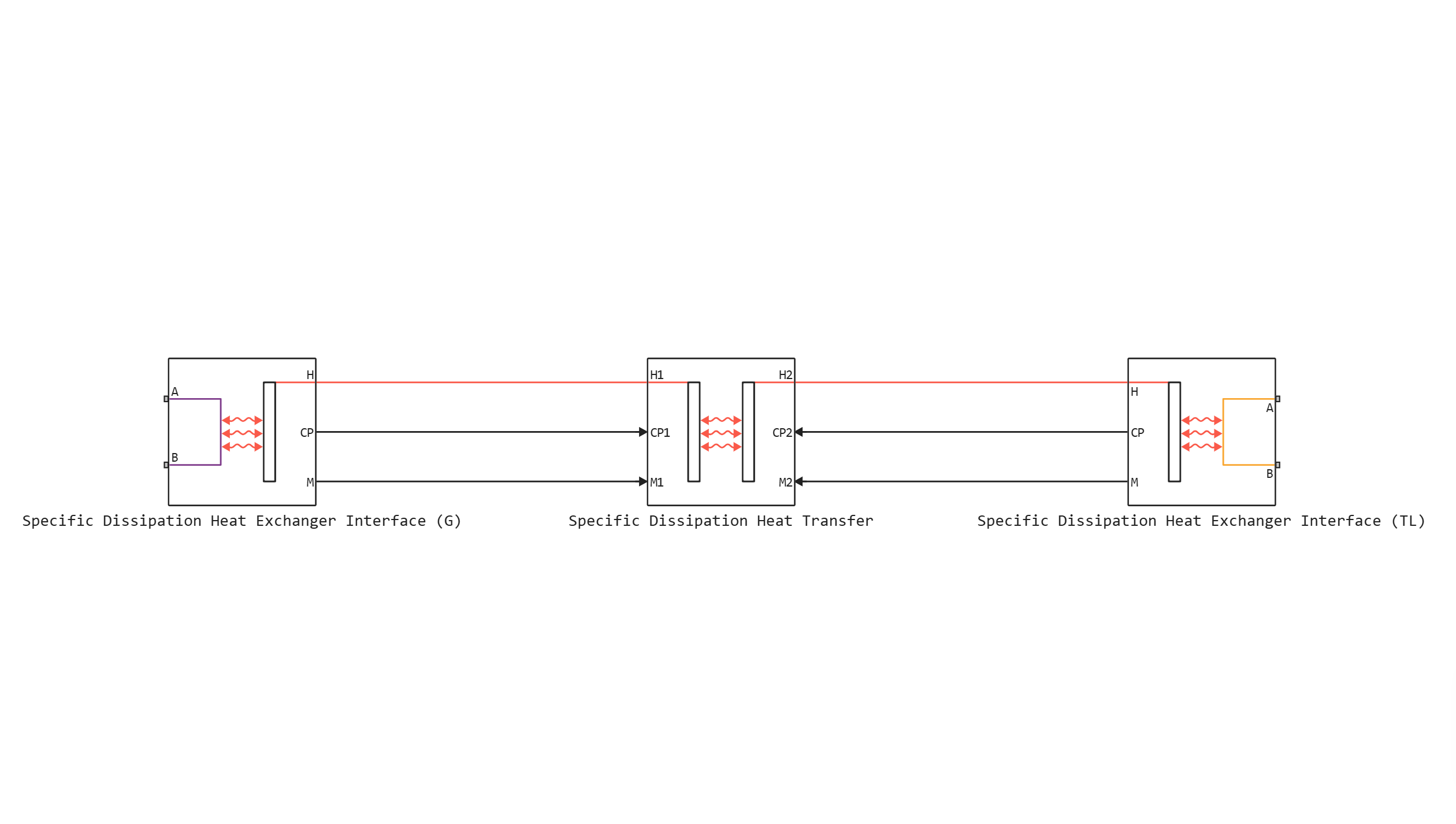
A block is a composite component built from simpler blocks. Block Specific Dissipation Heat Exchanger Interface (G) simulates the gas flow, and the block Specific Dissipation Heat Exchanger Interface (TL) — the flow of a thermally conductive liquid. The laws of conservation of mass, momentum, and energy in the passageways are determined by the corresponding interface blocks. Block Specific Dissipation Heat Transfer it takes into account the heat exchange through the wall between the streams.
Ports
Conserving
#
B1
—
gas inlet or outlet
gas
Details
The gas inlet or outlet port on the corresponding side of the heat exchanger.
| Program usage name |
|
#
A1
—
gas inlet or outlet
gas
Details
The gas inlet or outlet port on the corresponding side of the heat exchanger.
| Program usage name |
|
#
B2
—
inlet or outlet of the thermal liquid
thermal liquid
Details
The inlet or outlet port for the thermal liquid on the corresponding side of the heat exchanger.
| Program usage name |
|
#
A2
—
inlet or outlet of the thermal liquid
thermal liquid
Details
The inlet or outlet port for the thermal liquid on the corresponding side of the heat exchanger.
| Program usage name |
|
Parameters
Thermal liquid 2
#
Mass flow rate vector —
mass flow rate at each break point in the interpolation table for pressure drop
kg/s | kg/hr | kg/min | g/hr | g/min | g/s | t/hr | lbm/hr | lbm/min | lbm/s
Details
The mass flow rate at each break point in the interpolation table of differential pressure values. The unit uses linear interpolation and nearest neighbor extrapolation to obtain pressure drop values for any mass flow rate.
The mass flow values can be positive, zero, or negative and can cover laminar, transient, and turbulent zones. The vector must contain the same number of elements as the parameter. Pressure drop vector, and these elements should monotonously increase from left to right.
| Units |
|
| Default value |
|
| Program usage name |
|
| Evaluatable |
Yes |
#
Thermal Liquid 2 volume —
the volume of liquid in the channel for supplying heat-conducting liquid
m^3 | um^3 | mm^3 | cm^3 | km^3 | ml | l | gal | igal | in^3 | ft^3 | yd^3 | mi^3
Details
The volume of liquid in the channel for supplying heat-conducting liquid.
| Units |
|
| Default value |
|
| Program usage name |
|
| Evaluatable |
Yes |
#
Reference inflow pressure —
the absolute inlet pressure assumed in the tabular data
Pa | uPa | hPa | kPa | MPa | GPa | kgf/m^2 | kgf/cm^2 | kgf/mm^2 | mbar | bar | kbar | atm | ksi | psi | mmHg | inHg
Details
The absolute inlet pressure is determined by collecting tabular pressure drop data. The reference temperature and inlet pressure determine the density of the liquid assumed in the tabular data. During the simulation, the ratio of the reference density of the liquid to the actual one is multiplied by the differential pressure value shown in the table to obtain the actual pressure drop.
| Units |
|
| Default value |
|
| Program usage name |
|
| Evaluatable |
Yes |
#
Cross-sectional area at ports A2 and B2 —
the cross-sectional area of the flow at the inlet and outlet of the passage channel
m^2 | um^2 | mm^2 | cm^2 | km^2 | in^2 | ft^2 | yd^2 | mi^2 | ha | ac
Details
The cross-sectional area of the flow at the inlet and outlet of the channel for supplying heat-conducting liquid. Ports in the same channel have the same size.
| Units |
|
| Default value |
|
| Program usage name |
|
| Evaluatable |
Yes |
#
Reference inflow temperature —
the absolute temperature at the inlet, accepted in the tabular data
K | degC | degF | degR | deltaK | deltadegC | deltadegF | deltadegR
Details
The absolute inlet temperature is determined by collecting tabular pressure drop data. The reference temperature and inlet pressure determine the density of the liquid assumed in the tabular data. During the simulation, the ratio of the reference density of the liquid to the actual one is multiplied by the differential pressure value shown in the table to obtain the actual pressure drop.
| Units |
|
| Default value |
|
| Program usage name |
|
| Evaluatable |
Yes |
#
Mass flow rate threshold for flow reversal —
upper bound of the numerically smoothed region for mass flow
kg/s | kg/hr | kg/min | g/hr | g/min | g/s | t/hr | lbm/hr | lbm/min | lbm/s
Details
The mass flow rate, below which its value is numerically smoothed to prevent discontinuities.
| Units |
|
| Default value |
|
| Program usage name |
|
| Evaluatable |
Yes |
#
Pressure drop vector —
pressure drop at each break point in the mass flow interpolation table
Pa | uPa | hPa | kPa | MPa | GPa | kgf/m^2 | kgf/cm^2 | kgf/mm^2 | mbar | bar | kbar | atm | ksi | psi | mmHg | inHg
Details
The pressure drop at each break point in the mass flow interpolation table. The unit uses linear interpolation and nearest neighbor extrapolation to obtain pressure drop values for any mass flow rate.
The pressure drop values can be positive, zero, or negative and can cover laminar, transient, and turbulent zones. The vector must contain the same number of elements as the parameter. Mass flow rate vector, and these elements should monotonously increase from left to right.
| Units |
|
| Default value |
|
| Program usage name |
|
| Evaluatable |
Yes |
Heat Transfer
#
Thermal Liquid 2 mass flow rate vector, mdot2 —
the mass flow rate of the heat-conducting liquid at each break point in the interpolation table for the relative heat transfer value table
kg/s | kg/hr | kg/min | g/hr | g/min | g/s | t/hr | lbm/hr | lbm/min | lbm/s
Details
The mass flow rate of the heat-conducting liquid at each break point in the interpolation table for the relative heat transfer value table. The unit interpolates and extrapolates the values of the break points to obtain the relative heat transfer value of the heat exchanger at any mass flow rate.
The mass flow values can be positive, zero, or negative, but they must monotonously increase from left to right. Their number should be equal to the number of columns in the parameter. Specific dissipation table, SD(mdot1, mdot2). If the table contains lines and columns, then the vector of mass flow values has a length of elements.
| Units |
|
| Default value |
|
| Program usage name |
|
| Evaluatable |
Yes |
#
Gas 1 mass flow rate vector, mdot1 —
the mass flow rate of gas at each break point in the interpolation table for the relative heat transfer value table
kg/s | kg/hr | kg/min | g/hr | g/min | g/s | t/hr | lbm/hr | lbm/min | lbm/s
Details
The mass flow rate of the gas at each break point in the interpolation table for the relative heat transfer value table. The unit interpolates and extrapolates the values of the break points to obtain a relative heat transfer value at any mass flow rate.
The mass flow values can be positive, zero, or negative, but they must monotonously increase from left to right. Their number should be equal to the number of lines in the parameter. Specific dissipation table, SD(mdot1, mdot2). If the table contains lines and For example, the vector of mass flow values must have a length of elements.
| Units |
|
| Default value |
|
| Program usage name |
|
| Evaluatable |
Yes |
#
Check if violating maximum specific dissipation —
the status of the warning about the relative heat transfer value exceeding the minimum flow heat capacity
None | Error
Details
A warning about the relative heat transfer value exceeding the minimum flow heat capacity. The flow heat capacity is the product of the mass flow rate and the relative magnitude of the heat transfer, and its minimum value is the smallest of the two flows. This minimum determines the relative amount of heat transfer for a heat exchanger with maximum efficiency and cannot be exceeded. For more information, see the description of the block. Specific Dissipation Heat Transfer.
| Values |
|
| Default value |
|
| Program usage name |
|
| Evaluatable |
No |
#
Specific dissipation table, SD(mdot1, mdot2) —
the relative value of heat transfer at each break point in the interpolation table of mass flow rates of gas and heat-conducting liquid
W/K | kW/K
Details
The relative value of heat transfer at each break point in the interpolation table of the mass flow rates of gas and heat-conducting liquid. The unit interpolates and extrapolates the values of the break points to obtain efficiency for any pair of mass flow rates of gas and heat-conducting liquid.
The values of the relative heat transfer value should not be negative. They should be aligned from top to bottom in the order of increasing mass flow in the channel for gas and from left to right in the order of increasing mass flow in the channel for heat-conducting liquid. The number of rows must be equal to the parameter size. Gas 1 mass flow rate vector, mdot1, and the number of columns corresponds to the size of the parameter Thermal Liquid 2 mass flow rate vector, mdot2.
If the heat transfer coefficients are specified in the technical data sheet of your heat exchanger, multiply them by the surface area to calculate the relative amount of heat transfer.
| Units |
|
| Default value |
|
| Program usage name |
|
| Evaluatable |
Yes |
Gas 1
#
Mass flow rate vector —
mass flow rate at each break point in the interpolation table for pressure drop
kg/s | kg/hr | kg/min | g/hr | g/min | g/s | t/hr | lbm/hr | lbm/min | lbm/s
Details
The mass flow rate at each break point in the interpolation table of differential pressure values. The unit uses linear interpolation and nearest neighbor extrapolation to obtain pressure drop values for any mass flow rate.
The mass flow values can be positive, zero, or negative and can cover laminar, transient, and turbulent zones. The vector must contain the same number of elements as the parameter. Pressure drop vector, and these elements should monotonously increase from left to right.
| Units |
|
| Default value |
|
| Program usage name |
|
| Evaluatable |
Yes |
#
Cross-sectional area at ports A1 and B1 —
the cross-sectional area of the flow at the inlet and outlet of the passage channel
m^2 | um^2 | mm^2 | cm^2 | km^2 | in^2 | ft^2 | yd^2 | mi^2 | ha | ac
Details
The cross-sectional area of the flow at the inlet and outlet of the gas supply channel. Ports in the same channel have the same size.
| Units |
|
| Default value |
|
| Program usage name |
|
| Evaluatable |
Yes |
#
Gas 1 volume —
the volume of liquid in the gas supply channel
m^3 | um^3 | mm^3 | cm^3 | km^3 | ml | l | gal | igal | in^3 | ft^3 | yd^3 | mi^3
Details
The volume of liquid in the gas supply channel.
| Units |
|
| Default value |
|
| Program usage name |
|
| Evaluatable |
Yes |
#
Pressure drop vector —
pressure drop at each break point in the mass flow interpolation table
Pa | uPa | hPa | kPa | MPa | GPa | kgf/m^2 | kgf/cm^2 | kgf/mm^2 | mbar | bar | kbar | atm | ksi | psi | mmHg | inHg
Details
The pressure drop at each break point in the mass flow interpolation table. The unit uses linear interpolation and nearest neighbor extrapolation to obtain pressure drop values for any mass flow rate.
The pressure drop values can be positive, zero, or negative and can cover laminar, transient, and turbulent zones. The vector must contain the same number of elements as the parameter. Mass flow rate vector, and these elements should monotonously increase from left to right.
| Units |
|
| Default value |
|
| Program usage name |
|
| Evaluatable |
Yes |
#
Reference inflow temperature —
the absolute temperature at the inlet, accepted in the tabular data
K | degC | degF | degR | deltaK | deltadegC | deltadegF | deltadegR
Details
The absolute inlet temperature is determined by collecting tabular pressure drop data. The reference temperature and inlet pressure determine the density of the liquid assumed in the tabular data. During the simulation, the ratio of the reference density of the liquid to the actual one is multiplied by the differential pressure value shown in the table to obtain the actual pressure drop.
| Units |
|
| Default value |
|
| Program usage name |
|
| Evaluatable |
Yes |
#
Mass flow rate threshold for flow reversal —
upper bound of the numerically smoothed region for mass flow
kg/s | kg/hr | kg/min | g/hr | g/min | g/s | t/hr | lbm/hr | lbm/min | lbm/s
Details
The mass flow rate, below which its value is numerically smoothed to prevent discontinuities.
| Units |
|
| Default value |
|
| Program usage name |
|
| Evaluatable |
Yes |
#
Reference inflow pressure —
the absolute inlet pressure assumed in the tabular data
Pa | uPa | hPa | kPa | MPa | GPa | kgf/m^2 | kgf/cm^2 | kgf/mm^2 | mbar | bar | kbar | atm | ksi | psi | mmHg | inHg
Details
The absolute inlet pressure is determined by collecting tabular pressure drop data. The reference temperature and inlet pressure determine the density of the liquid assumed in the tabular data. During the simulation, the ratio of the reference density of the liquid to the actual one is multiplied by the differential pressure value shown in the table to obtain the actual pressure drop.
| Units |
|
| Default value |
|
| Program usage name |
|
| Evaluatable |
Yes |
Effects and Initial Conditions
#
Gas 1 initial temperature —
the temperature in the gas supply channel at the beginning of the simulation
K | degC | degF | degR | deltaK | deltadegC | deltadegF | deltadegR
Details
The temperature in the gas supply channel at the beginning of the simulation.
| Units |
|
| Default value |
|
| Program usage name |
|
| Evaluatable |
Yes |
#
Thermal Liquid 2 initial temperature —
the temperature in the channel for the supply of heat-conducting liquid at the beginning of the simulation
K | degC | degF | degR | deltaK | deltadegC | deltadegF | deltadegR
Details
The temperature in the channel for the supply of heat-conducting liquid at the beginning of the simulation.
| Units |
|
| Default value |
|
| Program usage name |
|
| Evaluatable |
Yes |
# Thermal Liquid 2 dynamic compressibility — the ability to simulate pressure dynamics in a channel for supplying a heat-conducting liquid
Details
The ability to simulate pressure dynamics in a channel for supplying a heat-conducting liquid. If you uncheck this box, the block will remove the pressure derivatives from the equations of conservation of energy and mass of the components. The pressure inside the heat exchanger will be reduced to a weighted average of the two inlet pressures.
| Default value |
|
| Program usage name |
|
| Evaluatable |
No |
#
Gas 1 initial pressure —
pressure in the gas supply channel at the beginning of the simulation
Pa | uPa | hPa | kPa | MPa | GPa | kgf/m^2 | kgf/cm^2 | kgf/mm^2 | mbar | bar | kbar | atm | ksi | psi | mmHg | inHg
Details
The pressure in the gas supply channel at the beginning of the simulation.
| Units |
|
| Default value |
|
| Program usage name |
|
| Evaluatable |
Yes |
#
Thermal Liquid 2 initial pressure —
pressure in the channel for the supply of heat-conducting liquid at the beginning of the simulation
Pa | uPa | hPa | kPa | MPa | GPa | kgf/m^2 | kgf/cm^2 | kgf/mm^2 | mbar | bar | kbar | atm | ksi | psi | mmHg | inHg
Details
The pressure in the channel for the supply of heat-conducting liquid at the beginning of the simulation.
| Units |
|
| Default value |
|
| Program usage name |
|
| Evaluatable |
Yes |