Cartridge Valve Insert (IL)
Cartridge valve for flow control in the isothermal fluid network.
blockType: EngeeFluids.IsothermalLiquid.Valves.FlowControl.CartridgeInsert
|
Path in the library: |

Description
Block Cartridge Valve Insert (IL) simulates a cartridge valve for flow control in an isothermal fluid network. The valve seat can be conical or can be set by the user using analytical or tabular parameterization. The valve opens when the total pressure at ports A and B exceeds the value of the parameter Spring preload force and the pressure on port X.
The geometry of the block seat can be set as conical or custom. The selected seat geometry defines the sub-components that make up the block. In both configurations, the parameter Port A poppet to port X pilot area ratio sets the balance of forces in the base unit Cartridge Valve Actuator (IL).
Use the block Cartridge Valve Insert (IL) if flow control via a control pressure line is required. To do this, use the blocks Pressure-Compensated 3-Way Flow Control Valve (IL) or Pressure-Compensated Flow Control Valve (IL) to control the flow due to pressure drop or block Poppet Valve (IL) to control the valve opening with an external signal.
Conical valve seat
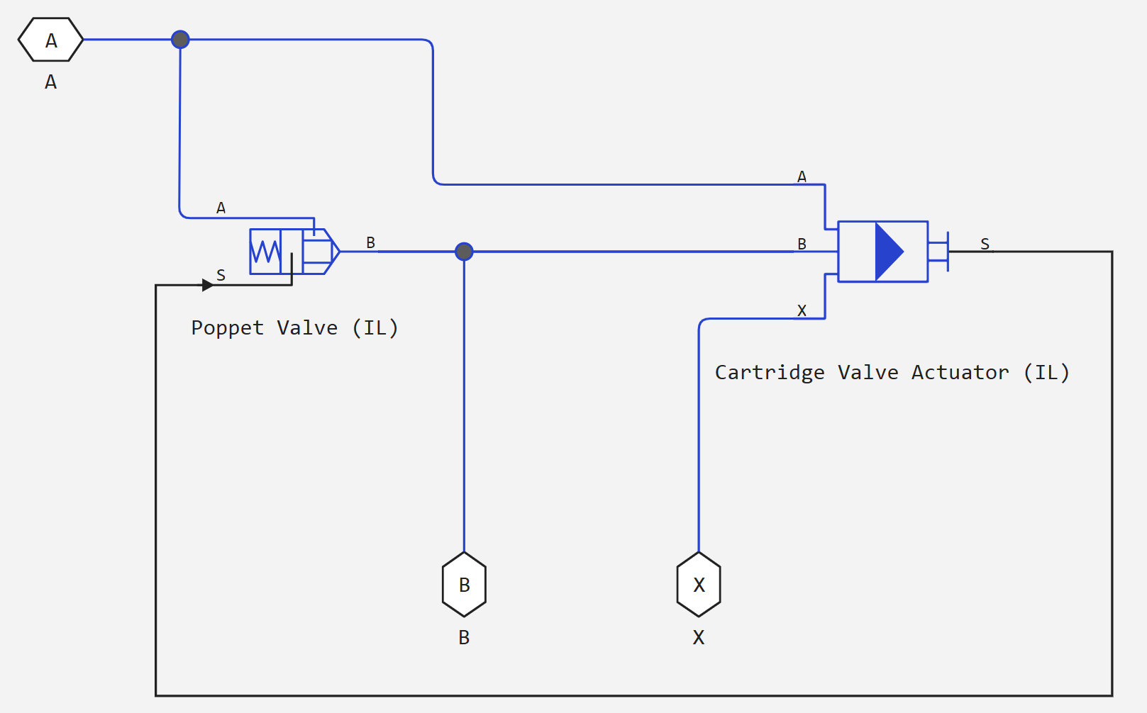
The cartridge valve with a conical seat is a component of two blocks:
_ Cartridge valve diagram with conical seat_
User-defined valve seat
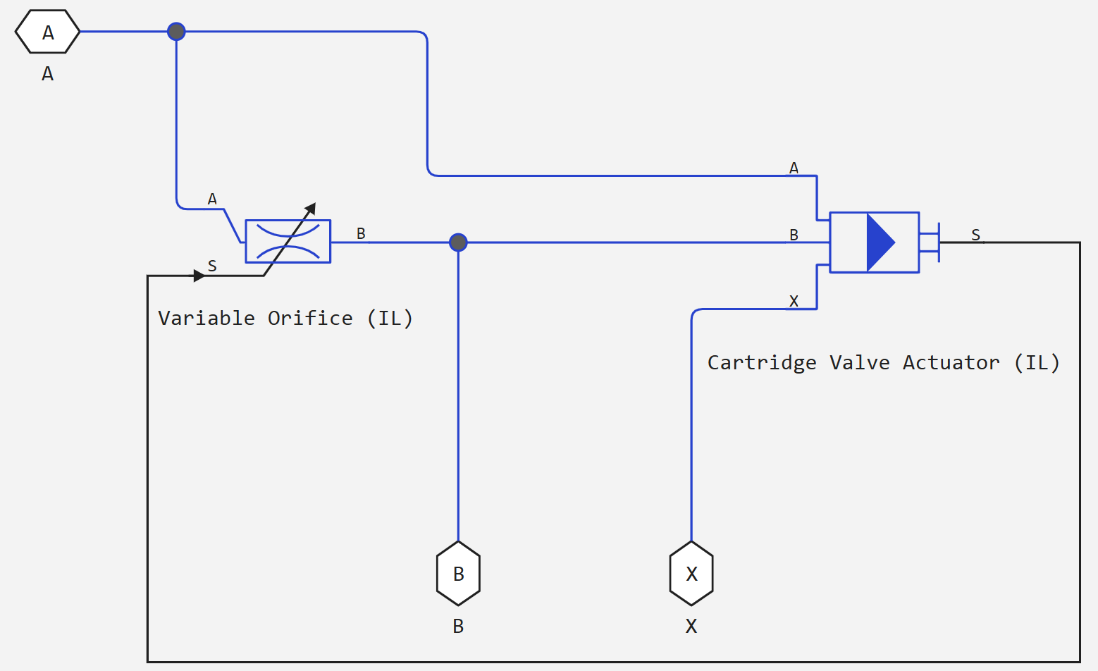
The cartridge valve with a custom seat is a two-block component:
_ Cartridge valve diagram with custom seat_
In the user configuration, you can set the valve opening parameters analytically or using a dataset.
analytical parameterization
If for the parameter Orifice parameterization the value is set Linear - Area vs. control member position, then the valve opening area is linearly proportional to the position of the control element. As soon as the pressure at port A or B exceeds the value Spring preload force, the valve opens before the value is reached Maximum orifice area. When the valve is fully closed, a small area Leakage area it remains open to the flow to preserve numerical continuity.
table parameterization
If for the parameter Orifice parameterization the value is set Tabulated data - Area vs. control member position, then the valve opening area can be set in the form of a table depending on the position of the control element. The block performs queries between data points using linear interpolation and uses linear extrapolation for points beyond the boundaries of the table.
If for the parameter Orifice parameterization the value is set Tabulated data - Volumetric flow rate vs. control member position and pressure drop, then the volume flow through the valve can be set in the form of a table depending on the position of the control element and the pressure drop across the valve. The block performs queries between data points using linear interpolation and uses linear extrapolation for points beyond the boundaries of the table. The volume flow rate is converted to the mass flow rate by multiplying by the density of the liquid.
Dynamics of the opening
If the dynamics of the opening is simulated, then a delay is introduced into the flow response to the simulated control pressure. Pressure It becomes a dynamic control pressure , otherwise — this is steady-state pressure. The instantaneous change in dynamic control pressure is calculated based on a time constant Valve opening time constant :
Numerical smoothing of force and discovery
When the drive is almost fully extended or retracted, and for the parameter Orifice parameterization the value is set Linear - Area vs. control member position, it is possible to maintain numerical stability in the simulation by adjusting the parameter Smoothing factor. The smoothing function is applied to the drive force and opening or hole area, but affects the simulation mainly at the extremes of these ranges.
The normalized force is
where
-
— power in port A;
-
— power on port B;
-
— parameter value Spring preload force;
-
— power on port X.
When for the parameter Valve seat specification the value is set Conical, the block provides a smooth change in the offset value of the control element between 0 and the maximum offset value. When for the parameter Valve seat specification the value is set Custom, the block provides a smooth change in the opening area between the parameter value Leakage area and the parameter value Maximum orifice area.
Ports
Conserving
#
B
—
Isothermal liquid port
Isothermal liquid
Details
A hole for the entry or exit of liquid.
| Program usage name |
|
#
X
—
pressure port
Isothermal liquid
Details
Control pressure port. There is no mass flow through port X.
| Program usage name |
|
#
A
—
Isothermal liquid port
Isothermal liquid
Details
A hole for the entry or exit of liquid.
| Program usage name |
|
Parameters
Main
#
Volumetric flow rate table, q(s,dp) —
table of volume flow values
m^3/s | mm^3/s | cm^3/s | m^3/hr | m^3/min | l/hr | l/min | l/s | gal/hr | gal/min | gal/s | ft^3/hr | ft^3/min | ft^3/s
Details
The matrix and volumetric flow rates based on independent values of the pressure drop and the position of the control element. Values and — the sizes of the corresponding vectors:
-
— the number of elements in the pressure drop vector Poppet position vector, s;
-
— the number of elements in the position vector of the control element Pressure drop vector, dp.
Dependencies
To use this parameter, set for the parameter Valve seat specification meaning Custom, and for the parameter Orifice parameterization meaning Tabulated data - Volumetric flow rate vs. control member position and pressure drop.
| Units |
|
| Default value |
|
| Program usage name |
|
| Evaluatable |
Yes |
#
Poppet position vector, s —
position vector of the control element
m | um | mm | cm | km | in | ft | yd | mi | nmi
Details
Vector of positions of control elements for tabular parameterization of volume flow. The position vector of the control elements corresponds to the pressure drop vector Pressure drop vector, dp and a table of volume flow values Volumetric flow rate table, q(s,dp). A positive displacement corresponds to the opening of the valve. The values are listed in ascending order, and the first element should be equal to 0. Linear interpolation is used between the data points in the table.
Dependencies
To use this parameter, set for the parameter Valve seat specification meaning Custom, and for the parameter Orifice parameterization meaning Tabulated data - Volumetric flow rate vs. control member position and pressure drop.
| Units |
|
| Default value |
|
| Program usage name |
|
| Evaluatable |
Yes |
#
Valve seat specification —
geometry of the valve seat
Conical | Custom
Details
Geometry of the valve seat. This parameter is used to calculate the open area between the control element and the seat.
| Values |
|
| Default value |
|
| Program usage name |
|
| Evaluatable |
No |
#
Orifice parameterization —
the method of calculating the area of the hole
Linear - Area vs. control member position | Tabulated data - Area vs. control member position | Tabulated data - Volumetric flow rate vs. control member position and pressure drop
Details
The method of calculating the area of the hole during modeling:
-
Linear - Area vs. control member position— the area is determined linearly depending on the position of the control element in relation to a fully open or fully closed valve. -
Tabulated data - Area vs. control member position— the hole area is interpolated from the parameter values provided by the user Poppet position vector and Orifice area vector based on the current position of the control element. -
Tabulated data - Volumetric flow rate vs. control member position and pressure drop— the volume flow rate is directly interpolated from the parameter values provided by the user Poppet position vector, s, Pressure drop vector, dp and Volumetric flow rate table, q(s,dp) based on the current position of the control element.
Dependencies
To use this parameter, set for the parameter Valve seat specification meaning Custom.
| Values |
|
| Default value |
|
| Program usage name |
|
| Evaluatable |
No |
# Discharge coefficient — expense ratio
Details
The correction factor is the ratio of the actual mass flow to the theoretical mass flow through the hole.
Dependencies
To use this parameter, set:
-
for the parameter Valve seat specification meaning
Conical; -
for the parameter Valve seat specification meaning
Custom, and for the parameter Orifice parameterization meaningLinear - Area vs. control member positionorTabulated data - Area vs. control member position.
| Default value |
|
| Program usage name |
|
| Evaluatable |
Yes |
#
Pressure drop vector, dp —
vector of pressure drop values
Pa | uPa | hPa | kPa | MPa | GPa | kgf/m^2 | kgf/cm^2 | kgf/mm^2 | mbar | bar | kbar | atm | ksi | psi | mmHg | inHg
Details
Vector of differential pressure values for tabular parameterization of volume flow. The pressure drop vector corresponds to the pressure drop vector Poppet position vector, s and a table of volume flow values Volumetric flow rate table, q(s,dp). The values are listed in ascending order, and the first element should be equal to 0. Linear interpolation is used between the data points in the table.
Dependencies
To use this parameter, set for the parameter Valve seat specification meaning Custom, and for the parameter Orifice parameterization meaning Tabulated data - Volumetric flow rate vs. control member position and pressure drop.
| Units |
|
| Default value |
|
| Program usage name |
|
| Evaluatable |
Yes |
# Port A poppet to port X pilot area ratio — the ratio of the area of the input port to the area of the control port
Details
The ratio of the area of the input port A to the area of the control port X. This value is used to calculate the force on port X. The ratio must be less than or equal to 1.
| Default value |
|
| Program usage name |
|
| Evaluatable |
Yes |
# Critical Reynolds number — upper limit of the Reynolds number for laminar flow
Details
The upper limit of the Reynolds number for laminar flow through the valve.
Dependencies
To use this parameter, set:
-
for the parameter Valve seat specification meaning
Conical; -
for the parameter Valve seat specification meaning
Custom, and for the parameter Orifice parameterization meaningLinear - Area vs. control member positionorTabulated data - Area vs. control member position.
| Default value |
|
| Program usage name |
|
| Evaluatable |
Yes |
#
Spring preload force —
spring force in the neutral position of the valve
N | nN | uN | mN | kN | MN | GN | dyn | lbf | kgf
Details
The force of the spring in the valve is due to the preload of the spring. This parameter is a threshold value that, when added to the control pressure at port X, balances the valve opening due to the pressures at ports A and B.
| Units |
|
| Default value |
|
| Program usage name |
|
| Evaluatable |
Yes |
#
Leakage area —
the gap area in the fully closed position
m^2 | um^2 | mm^2 | cm^2 | km^2 | in^2 | ft^2 | yd^2 | mi^2 | ha | ac
Details
The sum of all clearances when the valve is in the fully closed position. Any area less than this value is equal to the specified leakage area. This parameter contributes to numerical stability by maintaining continuity of flow.
Dependencies
To use this parameter, set:
-
for the parameter Valve seat specification meaning
Conical; -
for the parameter Valve seat specification meaning
Custom, and for the parameter Orifice parameterization meaningLinear - Area vs. control member position.
| Units |
|
| Default value |
|
| Program usage name |
|
| Evaluatable |
Yes |
#
Orifice area vector —
vector of values of the hole opening area
m^2 | um^2 | mm^2 | cm^2 | km^2 | in^2 | ft^2 | yd^2 | mi^2 | ha | ac
Details
A vector of hole area values for tabular parameterization of the hole area. The values in this vector correspond to the elements in Poppet position vector. The items are listed in ascending order and must be larger 0.
Dependencies
To use this parameter, set for the parameter Valve seat specification meaning Custom, and for the parameter Orifice parameterization meaning Tabulated data - Area vs. control member position.
| Units |
|
| Default value |
|
| Program usage name |
|
| Evaluatable |
Yes |
#
Spring stiffness —
the stiffness constant
N/m | mN/m | kN/m | MN/m | GN/m | kgf/m | lbf/ft | lbf/in
Details
The constant of spring stiffness.
| Units |
|
| Default value |
|
| Program usage name |
|
| Evaluatable |
Yes |
#
Poppet diameter —
diameter of the control element
m | um | mm | cm | km | in | ft | yd | mi | nmi
Details
The diameter of the valve control element.
Dependencies
To use this parameter, set for the parameter Valve seat specification meaning Conical.
| Units |
|
| Default value |
|
| Program usage name |
|
| Evaluatable |
Yes |
#
Maximum orifice area —
maximum opening area of the hole
m^2 | um^2 | mm^2 | cm^2 | km^2 | in^2 | ft^2 | yd^2 | mi^2 | ha | ac
Details
The cross-sectional area of the hole in the fully open position. This parameter is used as an upper limit for calculating the area and pressure during the simulation.
Dependencies
To use this parameter, set for the parameter Valve seat specification meaning Custom, and for the parameter Orifice parameterization meaning Linear - Area vs. control member position.
| Units |
|
| Default value |
|
| Program usage name |
|
| Evaluatable |
Yes |
#
Valve opening time constant —
valve time constant
s | ns | us | ms | min | hr | d
Details
A constant that determines the time it takes for a liquid to reach a stable state when moving from one position to another. This parameter affects the simulated opening dynamics.
| Units |
|
| Default value |
|
| Program usage name |
|
| Evaluatable |
Yes |
#
Seat cone angle —
angle of opening of the conical seat
rad | deg | rev | mrad | arcsec | arcmin | gon
Details
The opening angle of the conical seat.
Dependencies
To use this parameter, set for the parameter Valve seat specification meaning Conical.
| Units |
|
| Default value |
|
| Program usage name |
|
| Evaluatable |
Yes |
#
Poppet stroke —
cartridge valve stroke
m | um | mm | cm | km | in | ft | yd | mi | nmi
Details
The maximum possible displacement of the cartridge valve.
Dependencies
To use this parameter, set for the parameter Valve seat specification meaning Custom, and for the parameter Orifice parameterization meaning Linear - Area vs. control member position.
| Units |
|
| Default value |
|
| Program usage name |
|
| Evaluatable |
Yes |
#
Port A poppet area —
port cross-sectional area A
m^2 | um^2 | mm^2 | cm^2 | km^2 | in^2 | ft^2 | yd^2 | mi^2 | ha | ac
Details
The cross-sectional area of the port A.
| Units |
|
| Default value |
|
| Program usage name |
|
| Evaluatable |
Yes |
# Smoothing factor — numerical smoothing factor
Details
The continuous smoothing coefficient, which ensures smooth opening by correcting the valve characteristics in the almost open and almost closed positions. Set a non-zero value less than one to increase the stability of the simulation in these modes.
Dependencies
To use this parameter, set:
-
for the parameter Valve seat specification meaning
Conical; -
for the parameter Valve seat specification meaning
Custom, and for the parameter Orifice parameterization meaningLinear - Area vs. control member position.
| Default value |
|
| Program usage name |
|
| Evaluatable |
Yes |
#
Poppet position vector —
vector of positions of the control element
m | um | mm | cm | km | in | ft | yd | mi | nmi
Details
Vector of positions of the control element for tabular parameterization of the hole opening area. The elements of the vector must match the elements of the parameter Orifice area vector. The items are listed in ascending order and must be larger. 0.
Dependencies
To use this parameter, set for the parameter Valve seat specification meaning Custom, and for the parameter Orifice parameterization meaning Tabulated data - Area vs. control member position.
| Units |
|
| Default value |
|
| Program usage name |
|
| Evaluatable |
Yes |