Debugging the robot arm via COM
This example discusses debugging an advanced LART robot arm from Engee via a COM port. Engee generates signals - the rotation angles of the servos of the manipulator, and the robot's control unit processes the received signals and controls the position of the servos. Communication with low-level interfaces from Engee and the ability to change model parameters on the fly allows you to determine control boundaries and initial positions of servos during modeling.
Introduction
The purpose of the example is to debug the robot arm, namely, to adjust and optimize the mechanical and electrical parts, prepare a sketch for processing signals from Engee, and also use the Engee model and communication with external equipment to determine the initial positions of the servos, as well as the limits for adjusting their rotation angles.
The control object is a three-axis LART robot arm with a LART R-5M control unit, equipped with four servos: turning the crown, tilting and lifting the arm, and gripping. The microcontroller is a MEGA328P on an Arduino Nano board.
To control the manipulator, it is convenient to use the support of external equipment in Engee, for example, data transmission via COM. Thus, it is enough for Arduino to process the data obtained from the model to form the rotation angles of the axes.
The robot arm
Assembly Features
When assembling the mechanical part of the manipulator, the hinge forces were adjusted, the sg90 servos were replaced with mg90s - with the same size and supply voltage, they provide more torque. To ensure stable power supply to the servos, the galvanic cells have been replaced with a stabilized 5V power supply. In the example, the microcontroller is powered via USB from a computer.
The servos are connected to the pins of the control unit and, accordingly, the Arduino Nano as follows:
-
Basket rotation - D3;
-
Arm tilt - D5;
-
Hand removal - D6;
-
Capture - D9.
Arduino Sketch
A sketch uploaded to the Arduino to work with the manipulator - roboarm.ino. It connects the library Servo necessary for convenient operation with servos, the drives and the COM port are initialized, COM data is received in the cycle and the positions of the servos are set. Below you can read the contents of the file:
имя_файла = "roboarm/roboarm.ino" # @param {type:"string",placeholder:"roboarm/roboarm.ino"}
println(read(open(joinpath(@__DIR__, file_name)), String))
After assembly, connection of the manipulator, as well as assembly and compilation into the sketch controller, you can proceed to work with the Engee model.
The Engee example model
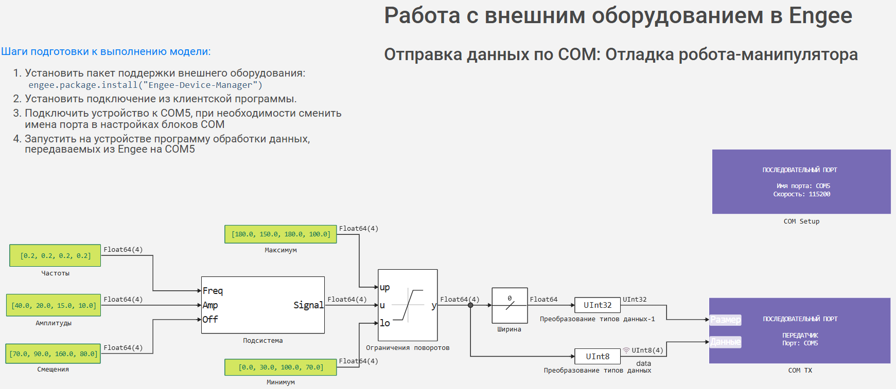
The model generates test signals for controlling the angles of servos according to the formula:
where - the correction factor of the signal frequency is determined empirically during debugging.
The vectors of amplitudes, frequencies, and offsets in the corresponding blocks are the parameters of the test signals that can be changed during the simulation process. The vectors of the maximum and minimum values of the test signals must be determined empirically during debugging. In addition, the displacement vector is the values of the initial conditions.
The received signals are transmitted via the COM port from Engee using the [COM TX] block(https://engee.com/helpcenter/stable/ru-en/hardware-com/com-tx.html ). The size of the array calculated by the Width block is passed to the first input. The data array itself is transmitted to the second input in the format UInt8. The COM connection is established using the [COM Setup] block (https://engee.com/helpcenter/stable/ru-en/hardware-com/com-setup.html ). The data transfer rate is 115200 baud, as defined in the Arduino sketch.
.png)
After that, you can connect the Engee to the COM port. The activation process is described in detail in примере.
The work of the model
Let's open and run the example model. The manipulator must be connected to a computer and to a voltage source, and the sketch must be uploaded to the controller. As a result, we should observe a change in the position of its joints. Manipulator control is shown in the recording below.
In recording using a code cell with a mask and program control the parameters are changed by the model on the fly. Graphical interface for controlling the frequency of change of servo angle signals:
    # @markdown **Basket rotation frequency:**
f_1 = 0.2 # @param {type:"slider",min:0.00,max:1.0,step:0.01}
    # @markdown **Frequency of hand tilt changes:**
f_2 = 0.2 # @param {type:"slider",min:0.00,max:1.0,step:0.01}
    # @markdown **The frequency of changing the outflow of the hand:**
f_3 = 0.2 # @param {type:"slider",min:0.00,max:1.0,step:0.01}
    # @markdown **Frequency of capture changes:**
f_4 = 0.2 # @param {type:"slider",min:0.00,max:1.0,step:0.01}

engee.set_param!("roboarm_test/Частоты", "Value"=>"[$Float64(f_1),$Float64(f_2),$Float64(f_3),$Float64(f_4)]")
engee.save(engee.gcm(), joinpath(@__DIR__, "roboarm_test.engee"); force = true);
Debugging process
During debugging, it is necessary to determine:
-
maximum and minimum rotation angles of servos,
-
the initial values of the servo angles.
To do this, it is necessary:
-
Determine the vector of values ** of frequencies** of test signals by the value
[0.0, 0.0, 0.0, 0.0]. -
Gradually change the values of each element of the vector of offsets test signals for the axis of rotation being debugged.
-
Fix the vectors of the maximum and minimum values of the rotation angles according to the mechanical limitations of the manipulator.
-
Fix the displacement vector ** by setting the desired initial position of the manipulator joints.
Conclusion
In this example, we have debugged the Engee model to control the LART robot arm by communicating with external equipment.
During the work, it was possible to determine the maximum and minimum values of the rotation angles of the servos, as well as their initial values. Next, you can proceed to the development of a control algorithm that implements a custom operating scenario for the manipulator.