Cosimulation of the "Universal Mechanism" and Engee: the oscillator
In this example, we will look at the integration of Engee with the Universal Mechanism (UM) software package using the example of cosimulation. Let's run a 3-D simulation of oscillator movement in the MIND, and in Engee, a model for generating the external force of the oscillator and reading variables from the MIND model.
Introduction
Co-simulation is the process of joint, synchronized modeling of an object/system or its component parts in different simulation systems. Using the built-in tools for working with [external hardware and software обеспечением](https://engee.com/helpcenter/stable/ru-en/engee-hardware/integration-with-hardware.html Engee has the opportunity to implement such a process.
The Universal Mechanism (UM) software package is designed to simulate the dynamics and kinematics of planar and spatial mechanical systems. In it, you can develop a 3-D mechanical system of any complexity, identify and calculate, as well as visualize the variables of the simulated system. In addition, the UM has tools for connecting external interfaces, described, for example, in specialized DLL libraries. We will use this method to implement the simulation.
The oscillator model in MIND
One of the basic examples of MIND modeling described in the user's guide is a load on a spring (or oscillator). By default, in the installed UM software package, it is located in the directory ...\UM Software Lab\Universal Mechanism\10\SAMPLES\TUTORIAL\oscillator\.
To work with the model, we will need two programs - UM Input for parameterizing the oscillator model and UM Simulation for modeling it. They are both available in the trial version of the software package [on the developer's website] (https://umlab.ru/pages/index.php?id=3 ).
During the simulation process, we will use the following UM Simulation tools:
-
Animation window
-
The Master of Variables
-
Graphic window
-
Object Modeling Inspector
The Engee model
The example model - universal_mechanism_oscillator.engee
The "Constant" blocks - Fx, Fy, Fz they will generate input values for the UM model. After they are added to the bus, they are transferred to the block UM Cosimulation from the "Hardware" section of the Engee block library. The same unit will transmit readable signals from the UM model. After the Bus Selection block, they are recorded for output to graphs.
.png)
UM and Engee integration
DLL library
A client-server DLL library is used to synchronize data reception/transmission from/to Engee Engee_UM.dll, working in the context of the integrating MIND solver. It defines the ports for receiving/transmitting data, in accordance with the ports specified in the block UM Cosimulation in the Engee model:
Signal reception port in the MIND: 7489
UM signal transmission port: 7490
This file must be saved on the computer where the simulation will be run in MIND. Next, we will use it when working with an external library from the UM.
Configuration file
The next step in preparing for simulation is to create and add a file with the name settings.cfg, which describes the main parameters of the signals - names, quantity, input values of the simulation parameters necessary for display in the MIND. The file for the current example is prepared in advance. It contains the following description of the signals:
MODEL_NAME OscillatorExample \
INPUT_SIGNAL_COUNT 3 \
OUTPUT_SIGNAL_COUNT 3 \
MODEL_PARAM_COUNT 3 \
INPUT_SIGNAL_NAMES dX dY dZ \
OUTPUT_SIGNAL_NAMES Fx Fy Fz \
MODEL_PARAM_NAMES Cx Cy Cz \
INIT_MODEL_PARAM 2000 2000 2000
This file must be placed in the folder with the UM Simulation executable file. umsimul.exe, by default it is:
C:\Program Files\UM Software Lab\Universal Mechanism\9\bin\umsimul.exe
Preparation of the oscillator model
Configure the input parameters of the oscillator model itself by following the following steps:
-
Let's open an example of an oscillator in UM Input.
-
Add a bipolar force, an "External force" with a linear character.
-
Application of force: Body1 - load (Brick), Body2 - suspension (Top).
-
Parameters
fx, fy, fzdetermine the Amplitude, Frequency, and Strength (F0) of the added force. -
Save the model.
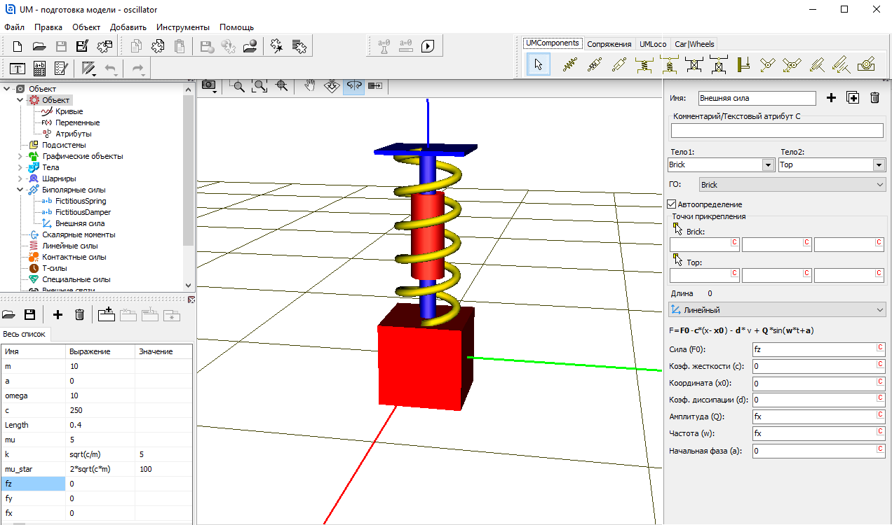
The added parameters fx, fy, fz will be passed to the UM model from Engee.
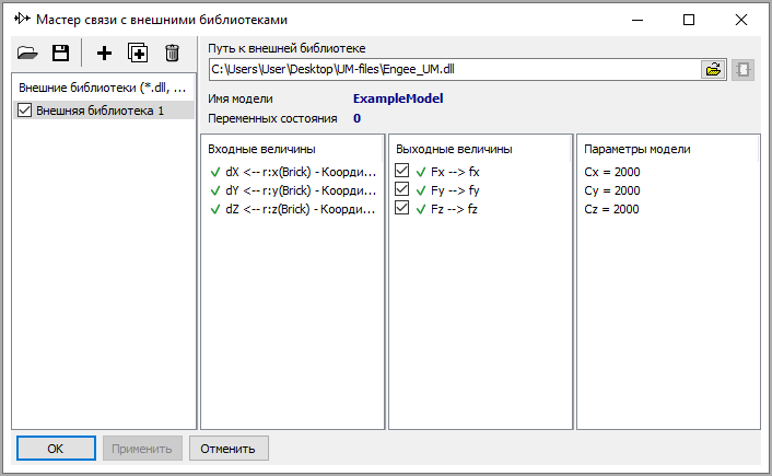
The wizard of communication with external libraries
Now we will establish a connection between the parameters of the UM model and the parameters configured earlier for receiving/transmitting from/to Engee. To do this, follow these steps:
-
Launch UM Simulation and open the oscillator model.
-
Open the Wizard for communicating with external libraries.
-
Adding the path to the external library
Engee_UM.dll. -
Select an external library, after which empty lines of input and output values will be displayed.
-
Open the Variable wizard, and transfer the projections of the load coordinates from the "Linear Variables" tab (
r:x(Brick), r:y(Brick), r:z(Brick)) in the input value lines (dX, dY, dZ) the communication wizard, and from the "All forces" tab - the parameters of the external forcefx, fy, fzto determine the output valuesFx, Fy, Fz. As a result, the configured connections in the wizard will be displayed as follows:
.png)
Engee Connection
To interact with the Engee server and the Universal Mechanism software installed on the user's computer, you must install the external hardware support package in Engee, download and run the client program. This process is described in detail in the example getting started with external оборудованием in Engee.
Cosimulation
Let's move on to the simulation. After preparing and configuring communication with Engee, we will perform the following steps:
-
Let's launch the Engee model.
-
According to the information message in the Engee client program window, we will make sure that the Um object has been created.
-
Let's start integrating into the MIND.
-
According to the information message in the Engee client program window, we will make sure that the interaction with Um has been successfully established.
Next, you can observe the cosimulation of the system in Engee and the Universal Mechanism.
In Engee, it is possible to change values on the fly, while the model will respond to changes in external influences. The entry below shows how changing the value of the projection of an external force on the Z axis affects the change in the coordinate of the oscillator along this axis.
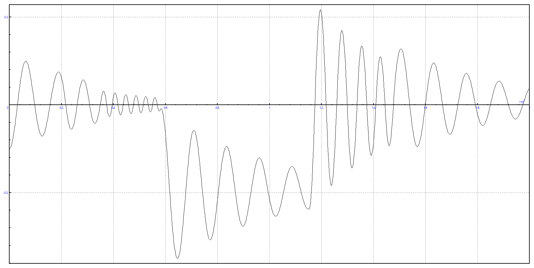
Simulation results
In Engee and the Universal Mechanism, there is a synchronous change in the graph of the load coordinate along the Z axis.:
Conclusion
In the example, we examined the integration process of Engee and the Universal Mechanism software package, and also performed a co-simulation of an oscillator with two-way data exchange.