Rapid prototyping of control algorithms on KPM RHYTHM: stepper motor
This example shows how to use a real-time machine, the KPM RHYTHM, in rapid prototyping control algorithms. The control object is a low-power stepper motor controlled by a two-shoulder dual MOSFET driver, the control signals are received and transmitted via the KPM RHYTHM GP-LC-45 digital input/output module.
Introduction
Rapid prototyping real-time control algorithms (Rapid control prototyping, RCP) is a modeling method that allows you to quickly evaluate the operation of control systems during their design. This approach allows for rapid iterations when developing control algorithms in a real environment, without having the professional skills of a programmer.
The principles of operation of the control object model, as well as the control system model, are described in detail in the example of full-step control of a bipolar stepper motor.
The next step in the development of a control system after modeling in Engee is the [rapid prototyping] stage1. It can be seamlessly implemented in Engee by switching the simulation environment to a real-time machine. To successfully set up and start working with KPM RHYTHM, it will be convenient to use the example Quick Start with KPM RHYTHM
Upon successful completion of the rapid prototyping and debugging of the control system on a real-time machine, it is possible to proceed to a full-fledged transfer of the control system to embedded systems. Engee allows you to automatically generate C code for embedding a management system model in custom projects for embedded systems. The example code generation for STM32 is dedicated to this process, which continues the current example.
The example model
The model of the original example is divided into two parts at this stage.:
- Prototype of the control system (subsystem
Control System) - The model of the control object (the circuit from the subsystem
Gate Driverbefore the signalsSpeedandPositionat the engine outlet)
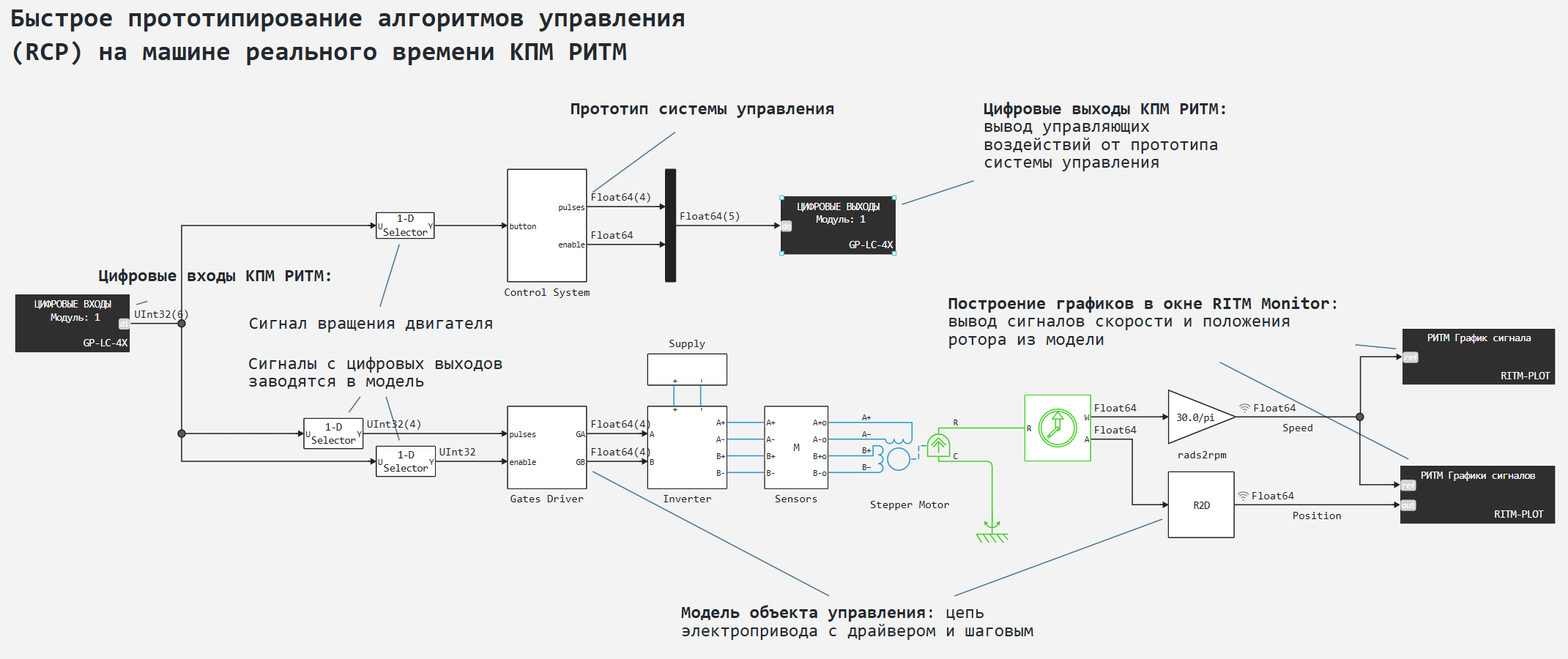
The input effect for the prototype control system is the "Start" signal to start the rotation of the stepper motor. The control system receives this signal from the digital input of the general-purpose peripheral module GP-LC-45 KPM RHYTHM.
The output effects of the control system model - the driver activation signal, as well as the driver key control signals are transmitted to the digital outputs of the same peripheral module.
In addition, the output signals from the control system model are transmitted to the control object model. For this purpose, the digital outputs of the peripheral module are connected to its digital inputs. They, in turn, input the received signals into the model of the control object.
The results of the model's operation - the recorded signals of the rotation speed and the angle of rotation of the stepper motor shaft are transmitted to the blocks C Function RITM-PLOT, which , during the execution of the model on a real-time machine , outputs graphs to the application RITM Monitor.
The KPM RHYTHM peripheral in the model
For working with a general-purpose peripheral module GP-LC-45 and its digital inputs and outputs in particular, the model uses the corresponding blocks from the section РИТМ Engee block libraries, with settings
- GP-LC-4x DI: module 1, 6 channels
- GP-LC-4x DO: module 1, 5 channels
Thus, in the module GP-LC-45 digital inputs are involved DI1-DI6 and digital outputs DO1-DO5
The block calculation step corresponds to the model calculation step (100 microseconds).
Blocks RITM-PLOT As mentioned above, signal graphs are displayed: 1 block is a graph of the shaft rotation speed, 2 blocks are graphs of the rotation speed and the angle of rotation of the shaft. The block calculation step is longer and takes 10 ms.
Connecting a management object
Module GP-LC-45 connected to a 37-pin terminal module GP-RT-Terminal-37 v1.0. To disconnect the circuits in this example, you need to use the pinout - pin assignment table of the terminal module.
The terminals used in this example are:
- 01 -
DGND(Digital earth) - 02 -
+3.3 V(3.3V power supply) - 35 -
DI6("Start" signal from push button contact) - 08 -
DO5(driver module activation signal) - 10, 29, 09, 28 -
DO1,DO2,DO3,DO4(driver key control signals) - 16 -
DI5(driver module activation signal for the control object model) - 18, 37, 19, 36 -
DI1,DI2,DI3,DI4(driver key management signals for the control object model)
The connection diagram of the terminal module and the elements of the control object is shown below.
After preparing the model and environment, as well as disconnecting all circuits and supplying power, we will proceed to executing the model on a real-time machine. This will allow us to debug control algorithms during rapid prototyping.
Model Execution
Let's run the model on KPM RHYTHM in the ["Interactive execution"] mode1. We will generate a "Start" signal by pressing the button contact. The following signal changes occur on the Engee model charts:
.png)
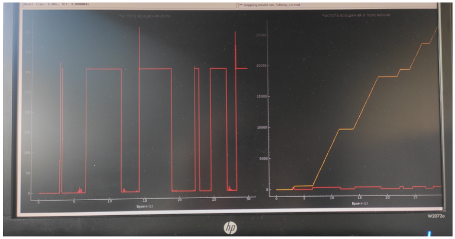
Similar graphs will be observed on the monitor screen connected to the real-time machine.:
.png)
At the same time, the rotation of the stepper motor shaft is observed with the naked eye.:
Conclusion
In the example, we used the approach of rapid prototyping of control algorithms based on a complex of semi-natural RHYTHM modeling. The initial model of the control system and facility was developed and debugged at Engee. At the current stage, we connected the control system with the peripheral modules of the real-time machine, and in parallel simulated the operation of the control object at a RHYTHM. The prototype control system reproduces identical and preset effects for engine control. Next, you can move on to transferring the control system to an embedded system.