Semi-natural simulation on KPM RHYTHM (Valve control via Modbus)
Introduction
In this example, modeling of a pipeline valve with an electric drive on a complex of semi-natural RHYTHM modeling is considered (КПМ РИТМ), while receiving and transmitting data between the operator and the Engee model is carried out using the Modbus TCP protocol.
Description of the model
The model of this example - test_SUI.engee. The control object is an electrically operated pipeline gate valve, which is enclosed in an activated subsystem. Valve. Activation signal enable it is equal to one if there is a voltage in the gate valve supply circuit (signal VoltageOK), correct phasing of the supply voltage (signal PhaseOK) and the absence of a control signal to stop the valve. Input signals for the subsystem - opening signals open and closure close latches. The simultaneous supply of these signals blocks a change in the position of the valve. Power supply in the control circuits is also required to provide opening/closing signals. The power check signal is simulated by the units CO_OK and CC_OK accordingly.
The example model implements two modes of operation - valve testing by simulation in Engee and operation on KPM RHYTHM in hard real-time mode. A variable is responsible for switching between modes mode. In the case mode = 1 the signals for opening/closing the gate valve come from the blocks Test_open and Test_close, the stop signal is from a variable stop, and when mode = 0 The control signals come from the peripheral units Modbus TCP. Variable stop the default value is "0". The mode and stop variables are set in the callbacks, the function PreLoadFunc.
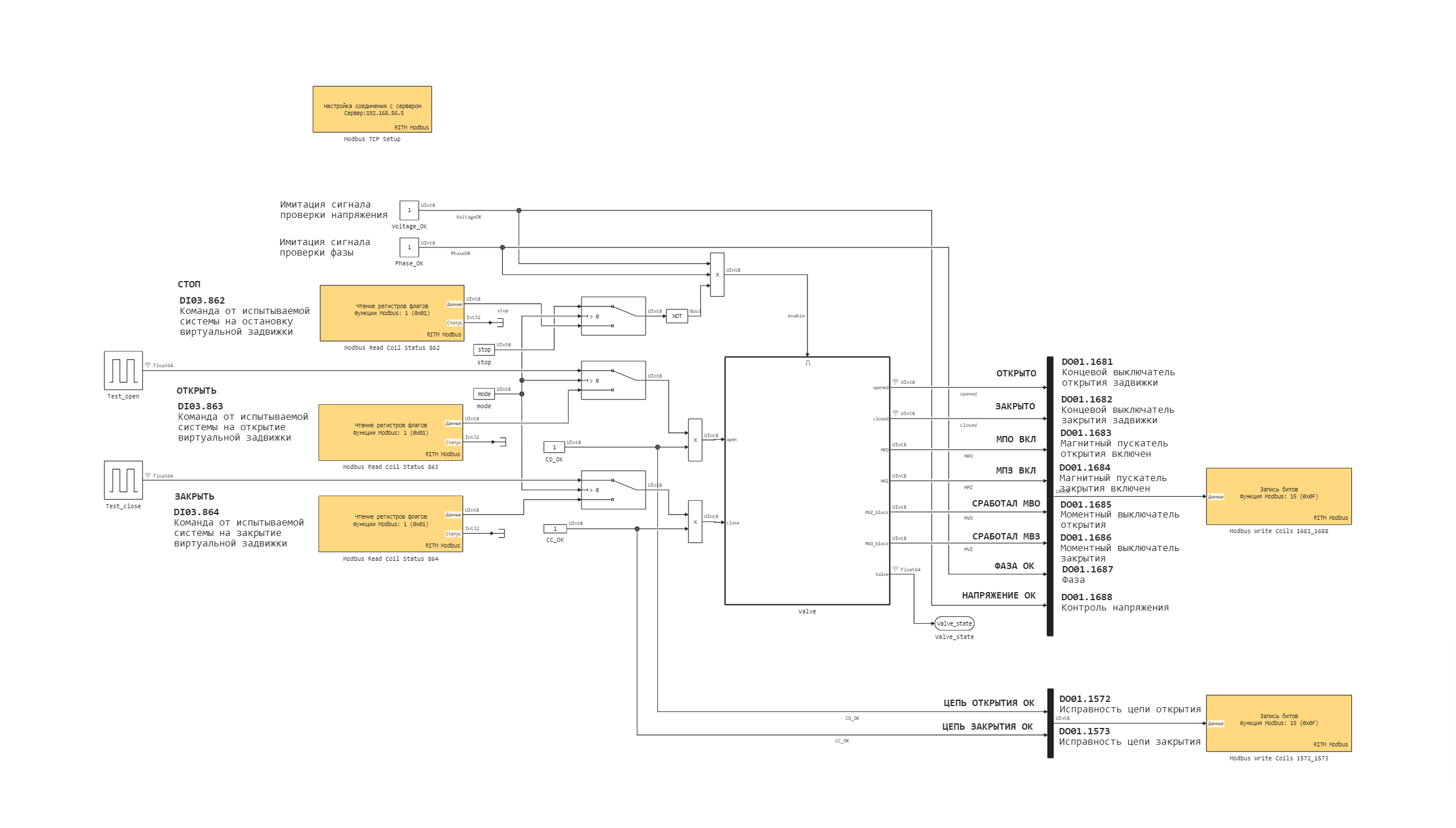
At the output of the subsystem, the gate valves are removed and output via Modbus TCP signals:
- Valve states:
opened(open) andclosed(closed), - switching on the magnetic opening/closing triggers:
MPO(MPO is enabled) andМПЗ(MPZ is enabled), - actuation of the opening/closing torque switches:
MVO(The MVO worked) andMVZ(The MVZ worked).
The signal Valve_position (gate valve position) is also captured at the subsystem output, but is not output via Modbus TCP.
In addition to the mentioned signals, Modbus TCP also outputs the following signals VoltageOK, PhaseOK, CO_OK and CC_OK.
Modbus Peripheral Units
For data transmission over Modbus TCP, the following peripheral units are used in the example KPM RHYTHM:
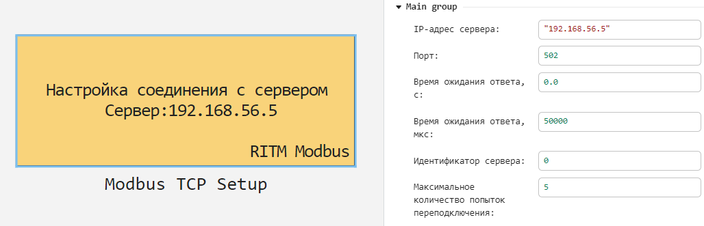
- Modbus TCP Setup - to configure the connection to the server,
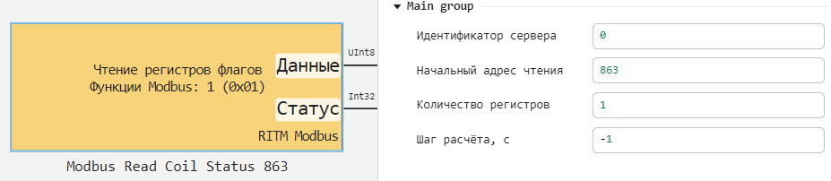
- Modbus Read Coil Status - for reading flag registers,
- Modbus Write Coils - for writing bits.
The connection settings block contains the IP address and port number, the waiting time for a response, and the number of reconnection attempts. The "Server ID" parameter is set to be the same for all peripheral units and can be used to work with multiple Modbus servers.
The initial read register and the number of registers to be read are set in the flag register reading blocks. In the example, these blocks transmit commands to the model for opening/closing and stopping the valve, recorded in registers at addresses 863, 864 and 862, respectively.
The start address and the number of bits to write from the model are set in the bit recording blocks. In the example, the model generates bits for writing to registers at addresses 1681-1688, 1572-1573.
Subsystem of the control object
Activated valve subsystem Valve It is shown in the picture below.
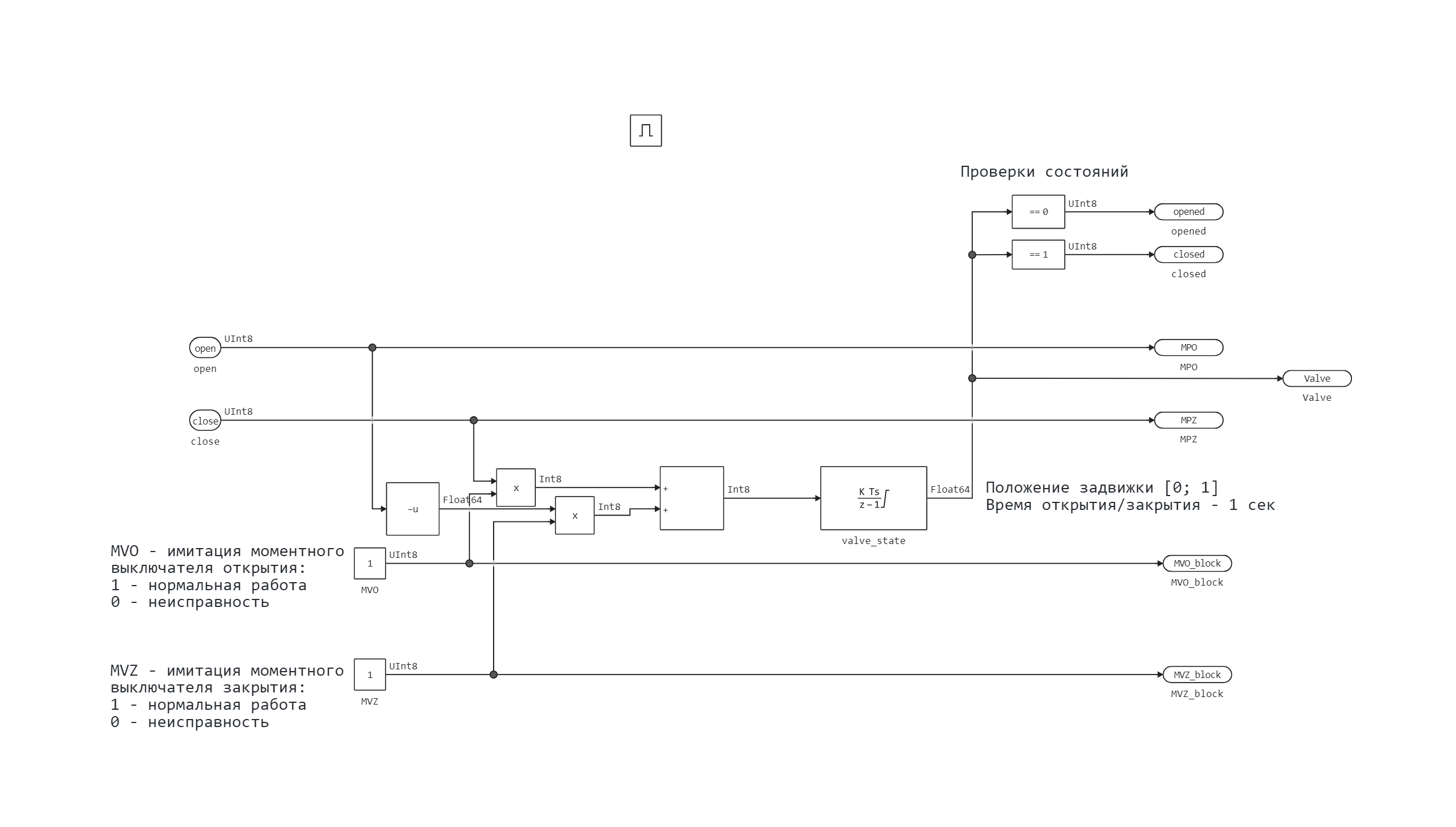
The operation of the gate valve is simulated by a linear inertial element with a restriction valve_state. So, when a signal is given to open/close the valve, it opens/closes in 1 second. The state "0" corresponds to the position "open", and "1" - "closed". The initial state is "closed". The subsystem also simulates the operation of torque switches (Blocks MVO and MVZ). The condition "1" corresponds to the normal operation of the gate valve, and "0" corresponds to torque overload and malfunction. In addition, the final states of the valve are checked in the subsystem.
Modeling in Engee
Let's download and execute the example model.
Путь_примера = "$(@__DIR__)";
Имя_модели = "test_SUI";
Путь_модели = joinpath(Путь_примера, Имя_модели*".engee")

if the model name is ∉ getfield.(engee.get_all_models(), :name)
    engee.load(Model path);
end

model = engee.run(Model name);
We get the model variables to build.
время = модель["valve_position"].time;
открытие = модель["test_open"].value;
закрытие = модель["test_close"].value;
положение_0 = модель["valve_position"].value;
открыто_0 = модель["opened"].value;
закрыто_0 = модель["closed"].value;

length = length(position_0)
position = Vector{Float64}(undef, length)
open = Vector{Float64}(undef, length)
closed = Vector{Float64}(undef, length)

for i in 1:length
    position[i] = position_0[i][1]
    open[i] = open_0[i][1]
    closed[i] = close_0[i][1]
end
We will plot the opening and closing schedules of the valve - we will output the test signals for opening and closing, the position of the valve and the final states.
using Plots
gr(size=(1000,300), xlims = (0,10))

график_1 = plot(время, [открытие, положение, открыто]; title = "Opening the gate valve")
график_2 = plot(время, [закрытие, положение, закрыто]; title = "Closing the gate valve")
plot(график_1, график_2; layout = (1,2), label = ["The signal" "Position" "Condition"])
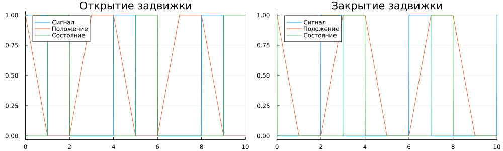
As can be seen from the graphs, the valve model performs opening and closing with a given inertia.
The work of the KPM RHYTHM model
Before starting the execution of the model on KPM RHYTHM, you need to make sure that the connection is correct, after which we will switch to the [interactive execution] mode(https://engee.com/helpcenter/stable/en/ritm/build-modes.html ) models.
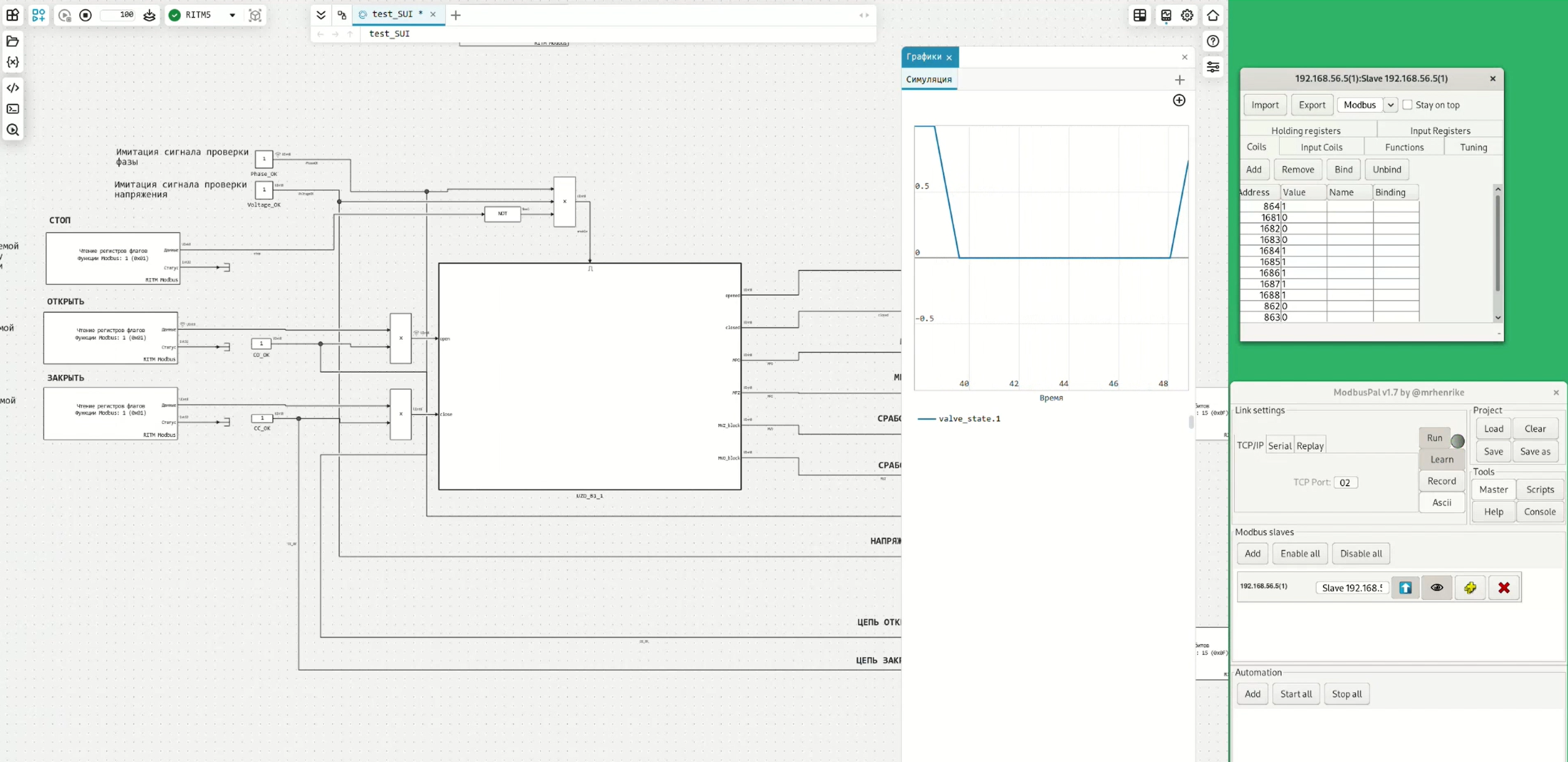
The considered model is executed on a KPM RHYTHM in real time for 100 seconds. During the operation of the model, data is exchanged over Modbus TCP with the ModbusPal simulator.
The recording of the operation of the valve model on the RHYTHM is shown in the animation ritm_valve_record.gif.
.png)
When the opening signal for tag 863 is applied, the bit for tag 1683 is set, which indicates that the magnetic valve opening starter is turned on. In this case, the position of the valve changes. After 1 second, the bit for tag 1681 is set, which indicates that the valve is fully open. When a signal is given to close the valve by tag 864, the bit by tag 1684 of the magnetic starter is first set, and after 1 second the closing limit switch is triggered, setting the bit by tag 1682. When the valve stop signal is applied (tag 862), the operation of the valve is blocked, and the opening/closing signals do not lead to any effects.
Conclusion
In the example, the Engee model for an electrically driven pipeline gate valve was considered, performed on KPM RHYTHM in real time. The gate valve is controlled and its states are read using the Modbus TCP protocol.