Frost Beamformer
Non-tunable directional pattern shaper.
blockType: FrostBeamformer
|
Path in the library: |

Description
Block Frost Beamformer implements a non-tunable directional pattern generator. The unit includes a time-domain MVDR beamformer based on groups of FIR filters. The MVDR shaper directs the beam in a given direction, and FIR filters preserve the input signal power.
Ports
Entrance
X — input signal
complex matrix M by N | real matrix M by N
The input signal is defined as a matrix M by N, where M is the number of signal samples, and N is the number of elements in the antenna array.
Data types: Float16, Float32, Float64, Int8, Int16, Int32, Int64, UInt8, UInt16, UInt32, UInt64, Bool
Support for complex numbers: Yes
XT — training signal
complex matrix M by N | real matrix M by N
The input signal is defined as a matrix M by N, where M is the number of signal samples, and N is the number of elements in the antenna array.
Dependencies
To use this port, select the Enable training data input checkbox.
Data types: Float16, Float32, Float64, Int8, Int16, Int32, Int64, UInt8, UInt16, UInt32, UInt64, Bool
Support for complex numbers: Yes
Ang — direction of pass beam formation:q[<br>] a 2-by-1 real vector
The direction of ray formation, defined as a 2-by-1 real vector having the form [AzimuthAngle;ElevationAngle]. The angle measurement units are degrees. The azimuth angle should be in the range from -180° to 180° inclusive, and the elevation angle should be in the range from -90° to 90° inclusive. The angles are set relative to the local coordinate system of the array.
Dependencies
To use this port, set the Source of beamforming direction parameter to Input port.
Data types: Float16, Float32, Float64, Int8, Int16, Int32, Int64, UInt8, UInt16, UInt32, UInt64, Bool
Output
Y is the output signal generated by the pass beam:q[<br>] complex vector M by 1
The output signal generated by the beam is returned as a complex vector by 1. Value — the number of signal samples.
Data types: Float16, Float32, Float64, Int8, Int16, Int32, Int64, UInt8, UInt16, UInt32, UInt64, Bool
Support for complex numbers: Yes
W — the weighting coefficients of the pass beam formation:q[<br>] an N-by-1 complex vector
The weighting coefficients during beam formation, returned as a complex vector N by 1. The value of N is the number of elements in the antenna array. If the Specify sensor array as parameter is set to Partitioned array or Replicated subarray, then N is the number of subarrays.
Dependencies
To use this port, select the Enable weights output checkbox.
Data types: Float16, Float32, Float64, Int8, Int16, Int32, Int64, UInt8, UInt16, UInt32, UInt64, Bool
Support for complex numbers: Yes
Parameters
Main
Signal propagation speed — signal propagation speed, m/s
3e8 (default) | positive scalar
The propagation velocity of the signal in the form of a real positive scalar. The default value for the speed of light is `3e8 m/s'.
The units of measurement are meters per second.
Data types: Float16, Float32, Float64, Int8, Int16, Int32, Int64, UInt8, UInt16, UInt32, UInt64
Inherit sample rate — inherit the sample rate of
enabled (by default) | disabled
Check the box to inherit the sampling rate from higher-level blocks. Otherwise, set the sampling rate using the Sample rate (Hz) parameter.
Sample rate (Hz) — pass sampling rate:q[<br>] 1e6 (default) | positive scalar
The sampling frequency of the signal in the form of a positive scalar. The units of measurement are hertz.
Dependencies
To use this option, uncheck the Inherit sample rate checkbox.
Data types: Float16, Float32, Float64, Int8, Int16, Int32, Int64, UInt8, UInt16, UInt32, UInt64, Bool
FIR filter length — the length of the FIR filter
1 (default) | positive integer
The length of the FIR filter used to process the signal from each element of the antenna array is set as a positive integer.
Data types: Float16, Float32, Float64, Int8, Int16, Int32, Int64, UInt8, UInt16, UInt32, UInt64, Bool
Diagonal loading factor — diagonal load factor to ensure pass stability:q[<br>] non-negative scalar
Specify the diagonal load factor as a non-negative scalar. Diagonal loading is a technique used to achieve reliable beamforming performance, especially when the training signal sample is small.
Enable training data input — the ability to use training data
disabled (by default) | enabled
Select this option to set additional training data via the input port `XT'. To use the input signal as training data, uncheck the box that removes this port.
Source of beamforming direction — source of the direction of ray formation
Property (default) | Input port
The source of the beamforming direction, specified as Property or Input port'. If the Source of beamforming direction parameter is set to `Property, then the direction is set using the Beamforming direction (deg) parameter. When the Input port value is selected, the direction is determined by the input to the Ang port.
Beamforming direction (deg) — direction of ray formation
a 2-by-1 real vector
The direction of ray formation, defined as a 2-by-1 real vector having the shape [AzimuthAngle;ElevationAngle]. The azimuthal angle should be in the range of −180°` to 180°. The elevation angle should be in the range of −90° to 90°. The angles are set relative to the local coordinate system of the array.
Dependencies
To use this parameter, set the Source of beamforming direction parameter to Property.
Enable weights output — option to output the weights of the pass beam shaper:q[<br>] disabled (by default) | enabled
Check this box to get the beam shaper weights from the output port. .
Simulate using — the Interpreted Execution (default) block modeling method
Block simulation, specified as Interpreted Execution or `Code Generation'. If you want your block to use the Engee interpreter, select `Interpreted Execution'. If you want your block to run as compiled code, select `Code Generation'. Compiled code takes time to compile, but is usually faster.
Interpreted execution is useful when designing and configuring a model. The block runs the base system object in Engee. You can quickly change and execute your model. When you are satisfied with the results, you can run the block using code generation. Long simulations run faster with Code Generation than with interpreted execution. You can perform repeated runs without recompilation, but if you change any block parameters, the block is automatically recompiled before execution.
This table shows how the Simulate using parameter affects the overall behavior of the simulation.
When the Engee model is in Accelerator mode, the block mode set using the Simulate using parameter overrides the simulation mode.
Acceleration Modes
Block simulation |
Type of simulation |
||
|
|
|
|
|
The block is executed using the Engee interpreter. |
The block is executed using the Engee interpreter. |
Creates an offline executable file from the model. |
|
The block is compiled. |
All the blocks in the model are compiled. |
|
Block parameter |
|
Type |
|
Values |
|
By default |
|
Sensor Array
Specify sensor array as — method for setting the pass array:q[<br>] Array (no subarrays) (default)
Specify a sensor element or array of sensors. The sensor array can also contain subarrays or be split into parts.
Available values:
-
Array (no subarrays)
Element
Element type — types of antenna array elements
Isotropic Antenna (default) | Cardioid Antenna | Cosine Antenna | Custom Antenna | Gaussian Antenna | Sinc Antenna | Omni Microphone | Custom Microphone
The type of antenna array element.
Available values:
-
Isotropic Antenna -
Cardioid Antenna -
Cosine Antenna -
Custom Antenna -
Gaussian Antenna -
Sinc Antenna -
Omni Microphone -
Custom Microphone
Operating frequency range (Hz) — operating frequency range of the pass antenna array element:q[<br>] [0,1e20] (default) | a real vector is a 1 by 2 row
The range of operating frequencies of the antenna array element in the form of a vector row 1 by 2 in the form of [LowerBound,UpperBound]. The element has no response outside this frequency range. The units of frequency measurement are Hz.
Dependencies
To use this parameter, set the Element type parameter to Isotropic Antenna, Cosine Antenna, or 'Omni Microphone'.
Baffle the back of the element — accounting for radiation through the rear beam of the radiation pattern into the rear hemisphere of the Isotropic Antenna element or Omni Microphone'
`disabled (by default) | enabled
`disabled (by default)
Set this flag to exclude radiation to the rear hemisphere. The response from the rear hemisphere at all azimuth angles outside the ±90° range from the wide side is set to zero. The wide-angle direction is defined as the azimuth angle of 0° and the elevation angle of 0°.
Dependencies
To use this parameter, set the Element type parameter to Isotropic Antenna or `Omni Microphone'.
Null axis direction — the direction of the axis along the zero radiation.
-x (default) | +x | +y | -y | +z | -z
The direction of the axis is along the zero radiation.
Dependencies
To use this parameter, set the Element type parameter to Cardioid Antenna.
Exponent of cosine pattern — exponent exponent when defining the shape of a cosine radiation pattern
[1.5, 1.5] (default) | non-negative scalar | a real matrix of non-negative values of 1 by 2
The exponent of the exponent of the cosine model in the form of a non-negative scalar or a 1 by 2 real matrix of non-negative values. If the Exponent of cosine pattern is a 1 by 2 vector, then the first element is the exponent in the direction of the azimuth, and the second is in the direction of the angle of the place. With a scalar value of this parameter, the cosines in the azimuthal and elevation directions are raised to one power.
Dependencies
To use this parameter, set the Element type parameter to `Cosine Antenna'.
Operating frequency vector (Hz) — array of operating frequencies of the antenna array element
[0,1e20] (default) | real vector is a string
An array of operating frequencies of an antenna array element in the form of a row vector 1 on increasing actual values. The element has no response beyond the frequency range specified by the minimum and maximum elements of this vector. The units of frequency measurement are Hz.
Dependencies
To use this parameter, set the Element type parameter to Custom Antenna or `Custom Microphone'. To set the responses at these frequencies, use the Frequency responses (dB) parameter.
Frequency responses (dB) — frequency responses of the antenna array element
[0,0] (default)| real vector string
The frequency response of the user elements of the antenna arrays is determined by the parameter Operating frequency vector (Hz). The dimensions of the Frequency responses (dB) vector must match the dimensions of the vector specified by the Operating frequency vector (Hz) parameter.
Dependencies
To use this parameter, set the Element type parameter to Custom Antenna or `Custom Microphone'.
Input Pattern Coordinate System — selection of the coordinate system of the radiation pattern of the user antenna
az-el (default) | phi-theta
The choice of the coordinate system of the radiation pattern of the user antenna is indicated by az-el or phi-theta'. When selecting `az-el, the Azimuth angles (deg) and Elevations angles (deg) parameters are used to set the coordinates of the directional pattern points. When specifying the phi-theta parameter, the Phi angle (deg) and Theta angles (deg) parameters are used to set the coordinates of the part points.
Dependencies
To use this parameter, set the Element type parameter to Custom Antenna.
Azimuth angles (deg) — azimuth angles of the antenna radiation pattern
[-180:180] (default) | real vector is a string
The values of the azimuth angles, which will be used to calculate the antenna pattern in the form of a vector row 1 on . it must be more than 2. The azimuth angles should be in the range of −180° up to 180° inclusive and arranged in strictly ascending order.
Dependencies
To use this parameter, set the Element type parameter to Custom Antenna and the Input Pattern Coordinate System parameter to az-el.
Elevation angles (deg) — values of the angles of the antenna pattern position
[-90:90] (default) | real vector is a string
The values of the angles of the location at which it is necessary to calculate the radiation pattern in the form of a vector 1 on . it must be more than 2. The units of measurement of angles are degrees. Elevation angles should be in the range of −90° to 90° inclusive and arranged in strictly ascending order.
Dependencies
To use this parameter, set the Element type parameter to Custom Antenna and the Input Pattern Coordinate System parameter to az-el.
Phi Angles (deg) — values of the Phi angles of the antenna radiation pattern
[0:360] (default) | real vector is row 1 on P
The angular coordinates of the Phi points where the antenna radiation pattern is set. They are defined as a real vector-row 1 on . it must be more than 2. The units of measurement of angles are degrees. The values of the Phi angles should be in the range from 0° to 360° and arranged in strictly ascending order.
Dependencies
To use this parameter, set the Element type parameter to Custom Antenna and the Input Pattern Coordinate System parameter to phi-theta.
Theta Angles (deg) — values of the angles of the Theta radiation pattern of the antenna
[0:180] (default) | real vector-row 1 on Q
The angular coordinates of the Theta points where the antenna radiation pattern is set. They are defined as a real vector-row 1 on . it must be more than 2. The units of measurement of angles are degrees. The values of the Theta angles must range from 0° to 180° and be arranged in strictly ascending order.
Dependencies
To use this parameter, set the Element type parameter to Custom Antenna and the Input Pattern Coordinate System parameter to phi-theta.
Magnitude pattern (dB) — the magnitude of the antenna radiation pattern
zeros(181.361) (default) | real matrix Q on P | real array Q on P on L
The value of the antenna pattern, set as a matrix on or an array on on .
-
If the Input Pattern Coordinate System parameter is set to `az-el', then is equal to the length of the vector defined by the Elevation angles (deg) parameter, in turn, — the length of the vector defined by the Azimuth angles (deg) parameter.
-
If the Input Pattern Coordinate System parameter is set to `phi-theta', then is equal to the length of the vector defined by the parameter Theta Angles (deg), in turn, — the length of the vector defined by the Phi Angles (deg) parameter.
Value is equal to the value of the Operating frequency vector (Hz) parameter.
-
If the value of this parameter is a matrix on , then the same scheme is applied for all frequencies specified in the parameter Operating frequency vector (Hz).
-
If the value is an array on on , each element on The array defines a template for the corresponding frequency specified in the parameter Operating frequency vector (Hz).
Dependencies
To use this parameter, set the Element type parameter to Custom Antenna.
Phase pattern (deg) — phase of the radiation pattern of the user antenna
zeros(181,361) (default) | real matrix Q on P | real array Q on P on L
The phase radiation pattern of the combined antenna, defined as a matrix on or an array on on .
-
If the Input Pattern Coordinate System parameter is set to `az-el', then is equal to the length of the vector defined by the Elevation angles (deg) parameter, in turn, — the length of the vector defined by the Azimuth angles (deg) parameter.
-
If the Input Pattern Coordinate System parameter is set to `phi-theta', then is equal to the length of the vector defined by the parameter Theta Angles (deg), in turn, — the length of the vector defined by the Phi Angles (deg) parameter.
Value is equal to the value of the Operating frequency vector (Hz) parameter.
-
If the value of this parameter is a matrix on , then the same scheme is applied for all frequencies specified in the parameter Operating frequency vector (Hz).
-
If the value is an array on on , each element on The array defines a template for the corresponding frequency specified in the parameter Operating frequency vector (Hz).
Dependencies
To use this parameter, set the Element type parameter to Custom Antenna.
Align element normal with array normal — align the normal of the antenna array element relative to the grid normal
enabled (by default) | disabled
If the parameter value is enabled, the radiation pattern of the antenna element is rotated to align with the normal of the array. If it is off, then the drawing of the element does not rotate.
If the antenna is used in an antenna array and the Input Pattern Coordinate System parameter has the value az-el, checking this box rotates the radiation pattern so that the x-axis of the element coordinate system points along the normal of the array. If there is no selection, the element template is used without rotation.
If the antenna is used in an antenna array and the Input Pattern Coordinate System parameter has the value phi-theta, checking this box rotates the radiation pattern so that the z axis of the element coordinate system points along the normal of the array.
Use this parameter together with the Array Normal parameter of the URA and UCA arrays.
Dependencies
To use this parameter, set the Element type parameter to Custom Antenna.
Radiation pattern beamwidth (deg) — the beam width of the antenna pattern
[10, 10] (default) | real scalar | a real vector is a 1 by 2 row
The beam width of the antenna pattern in degrees.
Dependencies
To use this parameter, set the Element type parameter to Gaussian Antenna.
Polar pattern frequencies (Hz) — frequency values for the polar pattern of the microphone
1e3 (default) | real scalar | real vector-row 1 on L
The frequency values for the polar radiation pattern are set as a real scalar or a real vector-row 1 on . The frequencies are in the frequency range specified by the parameter Operating frequency vector (Hz).
Dependencies
To use this parameter, set the Element type parameter to Custom Microphone.
Polar pattern angles (deg) — angle values for the polar radiation pattern of the microphone
[-180:180] (default) | real vector is row 1 on P
The angle values for the polar radiation pattern of the microphone are set as a vector . The angles are measured from the central axis of the microphone and should be in the range of −180° to 180° inclusive.
Dependencies
To use this parameter, set the Element type parameter to Custom Microphone.
Polar pattern (dB) — polar directional pattern of the microphone
zeros(1,361) (default) | real vector-row 1 on L
Set the value of the polar radiation pattern of the user microphone element in the form of a real vector-row 1 on , where — the number of frequencies specified in the parameter Polar pattern frequencies (Hz). The string represents the value of the polar radiation pattern measured at the corresponding frequency specified in the Polar pattern frequencies (Hz). The radiation pattern is measured in the azimuthal plane. In the azimuthal plane, the elevation angle is 0°, and the central axis is 0° in azimuth and 0° in elevation. The polar radiation pattern is symmetrical around the central axis. Based on the polar diagram, it is possible to construct a microphone directional pattern in three-dimensional space.
Dependencies
To use this parameter, set the Element type parameter to Custom Microphone.
Array
Geometry — geometry of the pass grid:q[<br>] ULA (default) | URA | UCA | Conformal Array
Antenna configuration, specified as:
-
'ULA' — uniform linear.
-
`URA' is a uniform rectangular shape.
-
'UCA' — uniform circular.
-
`Conformal Array' — arbitrary arrangement of elements.
Number of elements — number of elements in the pass antenna array:q[<br>] 2 for ULA arrays and 5 for UCA arrays (default)
The number of elements for a lattice of type ULA or UCA, set as an integer greater than or equal to 2.
Dependencies
To use this parameter, set the Geometry parameter to ULA or `UCA'.
Element spacing (m) — distance between pass elements:q[<br>] 0.5 for ULA arrays and [0.5,0.5] for URA arrays (default) | positive scalar | a 2-by-1 vector of positive values for URA arrays
The distance between adjacent array elements:
-
'ULA` — specify the distance between two adjacent array elements as a positive scalar.
-
URA' — the distance is set as a positive scalar or a vector of positive values 1 by 2. If Element spacing (m) is a scalar, then the distances between rows and columns are equal. If Element spacing(m) is a vector, then the vector has the form `[SpacingBetweenArrayRows,SpacingBetweenArrayColumns].
Dependencies
To use this parameter, set the Geometry parameter to ULA or `URA'.
Array axis — direction of the ULA pass linear axis:q[<br>] y (default) | x | z
The direction of the linear axis ULA, set as y, x or z. All elements of the ULA array are evenly distributed along this axis in the local coordinate system of the array.
Dependencies
-
To use this parameter, set the Geometry parameter to
ULA. -
This option is also enabled if the block supports only
ULAarrays.
Array size — grid dimensions URA'
`[2,2] (default) | positive integer | 1 by 2 vector with positive integer elements
`[2,2] (default)
The dimensions of the URA array, specified as a positive integer or a vector of 1 by 2 positive integers.
If the size of the array is a 1 by 2 vector, then the vector has the form [NumberOfArrayRows,NumberOfArrayColumns].
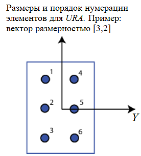
For URA, the array elements are indexed from top to bottom in the leftmost column of the array and then in the following columns from left to right.
Element lattice — grid of positions of elements URA
Rectangular (default) | Triangular
The grid of positions of the URA elements, set as rectangular or triangular.
-
'Rectangular' — aligns all elements in the row and column directions.
-
Triangular— shifts the elements of an even row of a rectangular grid towards the positive direction of the row axis. The offset is half the distance between the elements according to the size of the row.
Dependencies
To use this parameter, set the Geometry parameter to `URA'.
Array normal — direction of the normal to the pass grid:q[<br>] x for URA arrays or z for UCA arrays (default)
The direction of the normal to the grid, given as x, y, or z.
The elements of the flat grids lie in a plane orthogonal to the selected direction of the array normal. The side view directions of the elements are directed along the direction of the normal.
| The value of the normal to the grid | The position of the elements and the direction of the side view |
|---|---|
|
The elements of the lattice lie in - planes. All vectors normal to the elements are directed along the axis . |
|
The elements of the lattice lie in - planes. All vectors normal to the elements are directed along the axis . |
|
The elements of the lattice lie in - planes. All vectors normal to the elements are directed along the axis . |
Dependencies
To use this parameter, set the Geometry parameter to URA or `UCA'.
Radius of UCA (m) — the radius of the UCA pass grid:q[<br>] 0.5 (default) | positive scalar
The radius of the `UCA' array, set as a positive scalar.
Dependencies
To use this parameter, set the Geometry parameter to UCA.
Element positions (m) — the position of the elements of the conformal lattice
[0;0;0] ( by default) | matrix of positive values 3 by N
The positions of the elements of the conformal lattice, given as a matrix of real values of dimension 3 on , where – the number of elements in the conformal array. Each column of this matrix represents a position ['x';'y';'z'] of an array element in the local coordinate system of the array. The origin of the local coordinate system is (0,0,0). The units of measurement are meters.
Dependencies
To use this parameter, set the Geometry parameter to `Conformal Array'.
Element normals (deg) is the direction of the normal vectors of the elements of the conformal lattice
[0;0] | ` column vector 2 by 1` | matrix 2 by N
The direction of the normal vectors of elements in a conformal lattice, defined as a 2-by-1 column vector or a 2-by-1 matrix . indicates the number of elements in the array. If the parameter is a matrix, each column specifies the direction of the normal of the corresponding element in the form of [azimuth;elevation] relative to the local coordinate system. The local coordinate system aligns the positive axis with the direction of the normal to the conformal lattice. If the parameter value is a 2-by-1 column vector, the same pointing direction is used for all array elements.
Parameters of Element positions (m) and Element normals (deg) can be used to represent any arrangement in which pairs of elements differ by certain transformations. Transformations can combine translation, azimuth rotation, and elevation rotation. However, transformations that require rotation relative to the normal direction cannot be used.
To use this parameter, set the Geometry parameter to `Conformal Array'.
Taper — changing the radiation pattern of the elements of the antenna array
1 (default) | complex scalar | complex vector
The change in the radiation pattern of the antenna array elements is set as a complex scalar or a complex vector 1 by , where — the number of antenna array elements.
The coefficients that change the radiation pattern, also called element weights, multiply the responses of the antenna array elements. The coefficients change both the amplitude and the phase of the response to reduce the side lobes or the direction of the main axis of the response.
If the value of the Taper parameter is a scalar, then the same weight is applied to each element. If Taper is a vector, then a weight from the vector is applied to the corresponding element of the antenna array. The number of scales must correspond to the number of antenna array elements.