Continuous Wave (CE)
A source model with a constant envelope.
blockType: SubSystem
|
Path in the library: |

Description
Block Continuous Wave (CE) simulates constant modulation at a carrier frequency in a circuit envelope simulation environment. RF.
The block implements the ratio
or
on the carrier frequency depending on the type of source.
The block icon Continuous Wave (CE) It is dynamic and displays the current source type and the status of the noise parameter. This table shows how the block icon changes depending on the parameter values. Source type and Add phase noise.
| The flag Add phase noise | Source type: Ideal voltage |
Source type: Ideal current |
Source type: Power |
|---|---|---|---|
Not installed |
|
|
|
Installed |
|
|
|


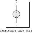
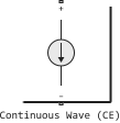
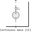
Parameters
Parameters
#
Source type —
source type
Ideal voltage | Ideal current | Power
Details
-
Ideal voltage— the unit simulates a constant voltage envelope on the parameters specified in the parameter Carrier frequencies, Hz carrier frequencies. The envelope has real and imaginary parts defined by the parameters Constant in-phase value, V and Constant quadrature value, V. -
Ideal current— the block simulates the DC envelope on the parameters specified in the parameter Carrier frequencies, Hz carrier frequencies. The envelope has real and imaginary parts defined by the parameters Constant in-phase value, A and Constant quadrature value, A. -
Power— the unit simulates a constant voltage envelopewhere
-
— the value of the parameter Available power;
-
— the value of the Source impedance (ohms) parameter;
-
— the value of the Angle (degrees) parameter.
-
| Values |
|
| Default value |
|
| Program usage name |
|
| Tunable |
No |
| Evaluatable |
Yes |
# Constant in-phase value, V — common-mode voltage component at carrier frequencies
Details
The value of the common-mode voltage component in volts, given as a real number.
Dependencies
To use this parameter, set for the parameter Source type meaning Ideal voltage.
| Default value |
|
| Program usage name |
|
| Tunable |
No |
| Evaluatable |
Yes |
# Constant in-phase value, A — common-mode component of current at carrier frequencies
Details
The value of the common-mode component of the current in amperes, given as a real number.
Dependencies
To use this parameter, set for the parameter Source type meaning Ideal current.
| Default value |
|
| Program usage name |
|
| Tunable |
No |
| Evaluatable |
Yes |
# Constant quadrature value, V — quadrature component of voltage at carrier frequencies
Details
The value of the quadrature component of the voltage in volts, given as a real number.
Dependencies
To use this parameter, set for the parameter Source type meaning Ideal voltage.
| Default value |
|
| Program usage name |
|
| Tunable |
No |
| Evaluatable |
Yes |
# Constant quadrature value, A — quadrature component of the current at carrier frequencies
Details
The value of the quadrature component of the current strength in amperes, given as a real number.
Dependencies
To use this parameter, set for the parameter Source type meaning Ideal current.
| Default value |
|
| Program usage name |
|
| Tunable |
No |
| Evaluatable |
Yes |
# Source impedance, Ohm — input resistance of the source
Details
The input resistance of the source in ohms, set as a positive real number. The value must be greater than or equal to 1e−18 Om.
Dependencies
To use this parameter, set for the parameter Source type meaning Power.
| Default value |
|
| Program usage name |
|
| Tunable |
No |
| Evaluatable |
Yes |
# Available power, W — available carrier frequency power
Details
Available power at carrier frequencies, specified as a vector of real numbers.
Dependencies
To use this parameter, set for the parameter Source type meaning Power.
| Default value |
|
| Program usage name |
|
| Tunable |
No |
| Evaluatable |
Yes |
# Angle, degrees — power phase angle
Details
The phase angles of power at carrier frequencies, given as a vector of real numbers.
Dependencies
To use this parameter, set for the parameter Source type meaning Power.
| Default value |
|
| Program usage name |
|
| Tunable |
No |
| Evaluatable |
Yes |
# Carrier frequencies, Hz — carrier frequency
Details
The carrier frequency, set as a positive real scalar.
| Default value |
|
| Program usage name |
|
| Tunable |
No |
| Evaluatable |
Yes |
# Add phase noise — adding phase noise
Details
Select this option to add phase noise to a system with a continuous signal source.
| Default value |
|
| Program usage name |
|
| Tunable |
No |
| Evaluatable |
Yes |
# Phase noise frequency offset, Hz — frequency shift of phase noise
Details
The frequency offset of the phase noise in Hz, specified as a scalar or vector.
The frequency offset values must be within the frequency band of the envelope used in the simulation. For more information, see the description of the block. Configuration (CE).
Dependencies
To use this option, check the box Add phase noise.
| Default value |
|
| Program usage name |
|
| Tunable |
No |
| Evaluatable |
Yes |
# Phase noise level, dBc/Hz — phase noise level
Details
The phase noise level in dBn/Hz, set as a scalar or vector.
The frequency offset values must be within the frequency band of the envelope used in the simulation. For more information, see the description of the block. Configuration (CE).
Dependencies
To use this option, check the box Add phase noise.
| Default value |
|
| Program usage name |
|
| Tunable |
No |
| Evaluatable |
Yes |
# Automatically estimate impulse response duration — automatic estimation of pulse response duration
Details
Select this option to automatically calculate the pulse response for phase noise. Uncheck this box to set the pulse response duration manually using the parameter Impulse response duration, s.
Dependencies
To use this option, check the box Add phase noise.
| Default value |
|
| Program usage name |
|
| Tunable |
No |
| Evaluatable |
Yes |
# Impulse response duration, s — duration of the impulse response
Details
The duration of the pulse response used to simulate phase noise, specified as a scalar in seconds. The impulse response cannot be set if the amplifier is non-linear.
| The frequency resolution of the phase noise profile is limited by the duration of the pulse response used to simulate it. Increase this duration to increase the accuracy of the phase noise profile. If the frequency offset resolution of the phase noise is too high for the specified duration of the pulse response, a warning message is displayed indicating the minimum duration required to achieve the required resolution. |
Dependencies
To use this option, uncheck the box. Automatically estimate impulse response duration.
| Default value |
|
| Program usage name |
|
| Tunable |
No |
| Evaluatable |
Yes |