EngeePhased.PhaseShiftBeamformer
|
Page in progress. |
A narrow-band beam shaper based on phase shift.
| Library |
|
| Block |
Description
System object EngeePhased.PhaseShiftBeamformer simulates a narrow-band beam shaper based on a phase shift. The delay is approximated using a phase shift in the time domain. The phase shifting beamformer belongs to the family of conventional beamformers.
To create and use a narrow-band phase shift beam shaper, follow these steps:
-
Create an object EngeePhased.PhaseShiftBeamformer and set its properties.
-
Call the object with arguments as if it were a function.
To learn more about how to work with system objects, see Engee System Objects.
Syntax
Creation
-
beamformer = EngeePhased.PhaseShiftBeamformer()— creates a phase shift based beamformer with default property values. -
beamformer = EngeePhased.PhaseShiftBeamformer(Name=Value)— creates a phase shift beam shaper with specified properties in the form of a pairName=Value, whereName— the name of the property, andValue— the appropriate value. You can specify multiple pairs «name-value» the order of the pairs does not matter. Unspecified properties retain their default values.
Using
-
Y = beamformer(X)— generates a narrow-band beam Y based on the phase shift X. To use this syntax, set the DirectionSource value"Property"and set the direction of ray formation using the Direction. -
Y = beamformer(X,ANG)— uses the input argument ANG to set the direction of ray formation. To use this syntax, set the DirectionSource value"Input port". -
Y,W = beamformer(___)— returns the weighting coefficients of the beamforming W. To use this syntax, set the WeightsOutputPort valuetrue.
Arguments
Input arguments
X — input signal
+
the complex matrix M by N
Details
The input signal, specified as a complex matrix on .
If the antenna array element contains antenna sublattices, — this is the number of antenna sublattices; otherwise — this is the number of antenna array elements.
The size of the first dimension of the input matrix can be changed to simulate a change in the length of the signal. A change in size can occur, for example, in the case of a pulse waveform with a variable pulse repetition rate.
| Типы данных |
|
| Support for complex numbers |
Yes |
ANG — output signal generation directions
+
The real vector is a 2-by-1 column | the real matrix 2 on L
Details
The radiation directions of the signals, specified as a real column vector on or the matrix on , where — this is the number of beam formation directions. Each column has the form [AzimuthAngle;ElevationAngle].
The units of measurement are degrees.
The azimuthal angle should lie between −180° and 180°, inclusive. The angle of the seat should be in the range of −90° before 90°, inclusive.
Dependencies
To use this argument, set the property to DirectionSource value "Input port".
| Типы данных |
|
Output arguments
Y is the output signal generated by the beam
+
the complex matrix M on L
Details
Superposition of input signals returned as a complex matrix on , where — the number of lines of the argument X, and — the number of beam formation directions.
| Типы данных |
|
| Support for complex numbers |
Yes |
W — the weighting coefficients of the beam formation
+
the complex N-by-L matrix
Details
Complex conjugate beamforming weights returned as a complex matrix on , where — the number of antenna array elements, — the number of beam formation directions.
Dependencies
To use this argument, set the following properties DirectionSource value true.
| Типы данных |
|
| Support for complex numbers |
Yes |
Features
#
DirectionSource —
source of the beam formation direction
String
Details
The source of the direction of beamforming, specified as "Property" (By default) or "Input port":
-
"Property"— specify the direction of beamforming using the property Direction -
Input port— specify the direction of beamforming using the input argument ANG
#
WeightsNormalization —
an approach to normalizing the weighting coefficients of the beamformer
String
Details
An approach to the normalization of the weighting coefficients of the beam shaper.
-
If this property is set to
"Distortionless"(By default), the gain in the direction of beamforming is0dB. -
If this property is set to
"Preserve power", the norm of the weighting coefficients is equal to one.
#
PropagationSpeed —
signal propagation speed
Real number
Details
The propagation velocity of the signal, given as a positive scalar. The speed of light is used By default 299792458.
Units of measurement — m/s.
#
OperatingFrequency —
Operating frequency
Real number
Details
The operating frequency specified as a positive scalar.
By default — 3e8.
Units of measurement — Hz.
#
WeightsOutputPort —
enabling the output of beamforming weights
Logical
Details
Enabling the output of the weighting coefficients of beamforming, is set as false (By default) or true. To get the beamforming weights, set this property to true and use the appropriate output argument, W.
If you don’t want to get weighting factors, set this property to false.
#
NumPhaseShifterBits —
the bit depth of the phase shifter quantization
Real number
Details
The number of bits used to quantize the phase shift component of the weighting coefficients of the beamforming vector or control vector is given as a non-negative integer. By default 0 means that quantization is not performed.
# SensorArray — antenna array object
Details
An object of an antenna array, an antenna made of sublattices, or an element of an antenna array. The antenna array may contain sublattices.
#
Direction —
beam formation directions
Scalar / array of real numbers
Details
Beamforming directions given as a real vector on or a real matrix on . In the matrix, each column specifies a separate direction of beamforming. Each column has the form [AzimuthAngle;ElevationAngle].
The azimuthal angle should lie between −180° and 180°, inclusive. The angle of the place should lie in the range of −90° before 90°, inclusive.
By default — [0; 0;;].
The units of measurement are degrees.
Dependencies
To use this property, set the property to DirectionSource value "Property".
Examples
Phase beam shaper using ULA, the direction of the beam formation using the property
Details
Let’s apply phase-shift beamforming to a sinusoidal signal received by a linear antenna array from 7 elements. The direction of the beam formation is azimuth 45° and the angle of the place 0°. Assume that the grid operates at a frequency of 300 MHz. We will specify the direction of the ray formation using the property.
Let’s simulate a sinusoidal signal coming to the grid.
using EngeePhased
using Random


t = collect(0:1000)
fsignal = 0.01
y = sin.(2π * fsignal .* t)

c = 299_792_458.0
fc = 300e6
incidentAngle = [45.0, 0.0]

array = EngeePhased.ULA(NumElements=7)
collector = EngeePhased.Collector(Sensor=array,OperatingFrequency=fc,PropagationSpeed=c)

x = collector(y, incidentAngle)

noise = 0.1 .* (randn(size(x)) .+ 1im .* randn(size(x)))
rx = x .+ noise
Let’s create a phase-shifting beam shaper, and then form a beam for the input data.
beamformer = EngeePhased.PhaseShiftBeamformer(SensorArray=array,
    OperatingFrequency=fc,PropagationSpeed=c,
    Direction=incidentAngle,WeightsOutputPort=true)
We will get the generated signal and the weighting coefficients of the beam shaper.
y,w = beamformer(rx)Let’s plot the original signal in the central element and the signal generated as a result of ray formation.
plot(t, real.(rx[:, 4]),
     seriestype = :line, ls = :dot, color = :red,
     label = "Original",
     xlabel = "Time", ylabel = "Amplitude")

plot!(t, real.(y),
      seriestype = :line, color = :blue,
      label = "Beamformed")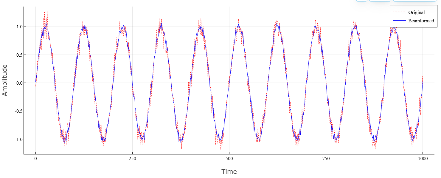
We will construct a radiation pattern of the antenna array after applying the weighting coefficients.
pattern(array,fc,[-180:180],0,PropagationSpeed=c,CoordinateSystem="polar",Weights=w)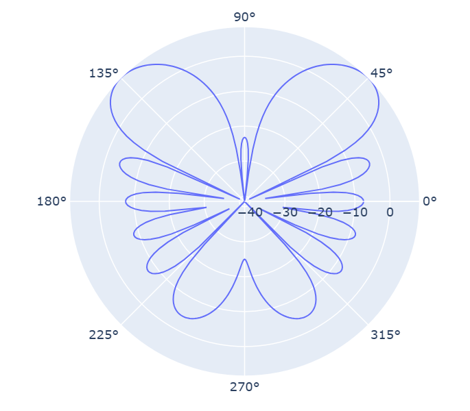
Phase beamformer using ULA, the direction of beamforming using the input argument
Details
Let’s apply phase-shift beamforming to the signal received by a linear antenna array from 5 elements. The direction of the beam formation is azimuth 45° and the angle of the place 0°. Assume that the grid operates at a frequency of 300 MHz. We will specify the direction of the ray formation using the input argument.
Let’s simulate a sinusoidal signal coming to the grid.
using EngeePhased
using LinearAlgebra
using Random

function collectPlaneWave(array, x, incidentAngle, fc, c)
    N = array.NumElements
    az = deg2rad(incidentAngle[1])
    el = deg2rad(incidentAngle[2])
    d = c / fc / 2
    u = cos(el) * cos(az)
    n = -(N-1)/2 : (N-1)/2
    a = exp.(+1im * 2π * (fc / c) * d .* n .* u)
    return vec(x) * transpose(a)
end


t = collect(0:1000)
fsignal = 0.01
x = sin.(2π * fsignal .* t)

c = 299_792_458.0
fc = 300e6
incidentAngle = [45.0, 0.0]

array = EngeePhased.ULA(NumElements=5)

x = collectPlaneWave(array, x, incidentAngle, fc, c)

noise = 0.1 .* (randn(size(x)) .+ 1im .* randn(size(x)))
rx = x .+ noise
Let’s create a phase-shifting beam shaper, and then form a beam for the input data.
beamformer = EngeePhased.PhaseShiftBeamformer(SensorArray=array,
    OperatingFrequency=fc,PropagationSpeed=c,
    DirectionSource="Input port",WeightsOutputPort=true)
We will get the generated signal and the weighting coefficients of the beam shaper.
y,w = beamformer(rx,incidentAngle)Let’s plot the original signal in the central element and the signal generated as a result of ray formation.
plot(t, real.(rx[:, 3]),
     seriestype = :line, ls = :dot, color = :red,
     label = "Original",
     xlabel = "Time", ylabel = "Amplitude")

plot!(t, real.(y),
      seriestype = :line, color = :blue,
      label = "Beamformed")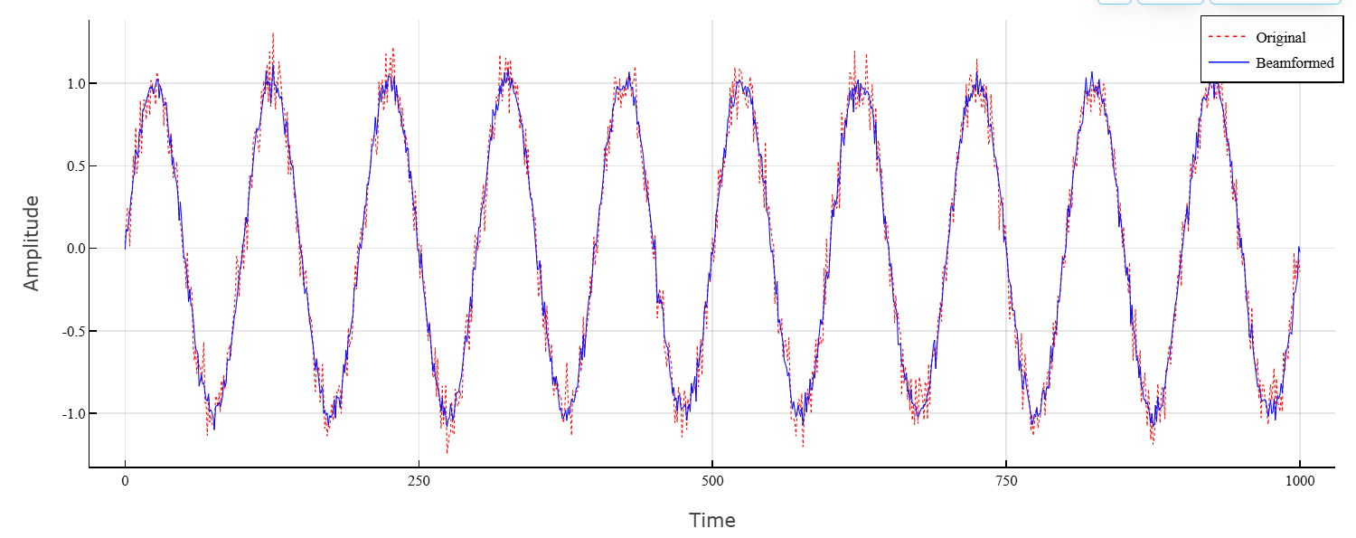
We will construct a radiation pattern of the antenna array after applying the weighting coefficients.
pattern(array,fc,[-180:180],0,PropagationSpeed=c,CoordinateSystem="rectangular",Weights=w)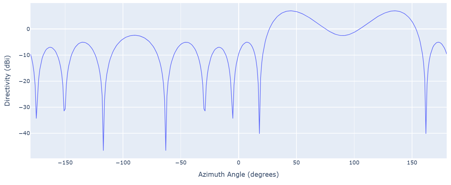
Additional Info
Phase shift beam formation
Details
The phase shift beamformer uses a conventional delayed-sum beamforming algorithm. When beamforming, it is assumed that the signal is narrowband, so a phase shift can approximate the required delay. At the same time, the beam shaper retains the power of the incoming signal.
For more information, see [1].
Data accuracy
Details
System object EngeePhased.PhaseShiftBeamformer supports single and double precision for inputs, properties, and arguments.
-
If the input data of the argument X has single precision, then the output data has single precision.
-
If the input data of the argument X has double precision, then the output data has double precision. The accuracy of the output data does not depend on the accuracy of the properties and other arguments.
Literature
-
Van Trees, H.L. Optimum Array Processing. New York, NY: Wiley-Interscience, 2002.
-
Johnson, Don H. and D. Dudgeon. Array Signal Processing. Englewood Cliffs, NJ: Prentice Hall, 1993.
-
Van Veen, B.D. and K. M. Buckley. Beamforming: A versatile approach to spatial filtering. IEEE ASSP Magazine, Vol. 5 No. 2 pp. 4–24.