Engee System Objects
This article describes a general approach to working with system objects in Engee. For information on a specific system object, please contact command line Engee  and in help mode? (click ? to switch to the mode), enter his name. and in help mode? (click ? to switch to the mode), enter his name.
|
A System object is an object of the Engee modeling environment that helps model dynamic systems. System objects are particularly useful for signal processing, communications, radar, and control tasks. They provide modularity and convenience when creating dynamic systems in Engee by providing simple tools for creating, configuring, and using components.
Using system objects allows you to model real objects using the principles of object-oriented programming (OOP). This ensures a smooth transition from engineering concepts to software models, which makes it possible to more efficiently organize work with objects in accordance with classical programming approaches.
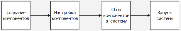
System objects are created and used in four stages:
-
Component creation — at the first stage, system objects are initialized, which represent the necessary components of the system. These objects can simulate signal generators, transmitters, receivers, and other devices. For example, an object is being created
waveformusing the classEngeePhase.RectangularWaveform(), representing a rectangular pulse generator. At this stage, blanks are created for future components, but still without detailed configuration.; -
Component Configuration — after creating an object, it is configured, where key parameters are set that determine the behavior of the component. This may include pulse repetition rate, signal strength, sampling rate, and other important characteristics.;
-
Assembling components into a system — At this stage, the configured components are combined into a single system where they can interact with each other, creating a data stream. This assembly allows you to organize the transmission and processing of signals between components, reflecting the physical processes that will occur during the operation of the system.;
-
System Startup — After completing the component assembly, the system is ready to perform operations. At this stage, all necessary calculations and signal transmission are performed.
An example of launching a radar system based on system objects (for more information, see The stages of creating a system based on system objects):
# Creating a signal generator (the first stage)
waveform = EngeePhased.RectangularWaveform()

# Setting up the signal generator (second stage)
waveform.PulseWidth = 100e-6;   # Pulse duration, 1 microsecond
waveform.PRF = 1e3;             # Pulse repetition rate, 1 kHz
waveform.SampleRate = 1e6;      # Sampling rate, 1 MHz

# Creating and configuring the transmitter (steps 1 and 2 together, alternative option)
transmitter = EngeePhased.Transmitter(
    PeakPower = 50,                  # Peak power, 50 Watts
    Gain = 40,                        # Gain, 40 dB
);

# Creating and configuring the receiver (steps 1 and 2 together, alternative option)
receiver = EngeePhased.ReceiverPreamp(
    SampleRate = 1e6,                # Sampling rate, 1 MHz
    NoiseFigure = 5,                 # Noise level, 5 dB
    NoiseMethod = "Noise power",     # The method of setting noise, power
    NoisePower = 50000,              # Noise power
);

# All previous stages form the 3rd point – the assembly of components into a system reflecting real physical processes.

# System startup (stage 4)
signal = step!(waveform);               # Generating another pulse
transmitted = transmitter(signal);      # Signal transmission
received = receiver(transmitted);       # Receiving a signal with added noise

# (Optional) Plotting of signals
plot(abs.(signal), title="Transmitted signal", label = false) |> display
plot(abs.(received), title="Received signal", label = false)
When system objects are called, data processing, initialization, and state management are performed, which simplifies the modeling of complex dynamic systems. In such systems, the output data depends not only on the current input values, but also on the previous state of the system. The system object retains this previous state in order to use it in the next stage of calculations.
The stages of creating a system based on system objects
Working with system objects in Engee includes several basic steps that help organize code into a logical structure, representing physical processes. Let’s look at an example of creating a simple TF single-position radar system, which will show how system objects are created and used.
Creating components
The first step is to create the basic objects that will represent the system components. Components are created using built-in Engee system classes representing various functional elements such as signal generators, transmitters, and receivers.
To see all the available options for configuring a component, create a component (execute the code) and in variable window  move the mouse cursor over the corresponding component:
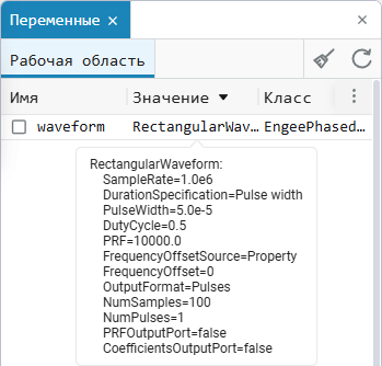
An example of creating a rectangular pulse generator:
waveform = EngeePhased.RectangularWaveform()Here EngeePhased.RectangularWaveform — this is a class representing a rectangular pulse generator. An object waveform It will become the basis for generating signals that will be transmitted through the system. At this stage, only the object itself is created, without specifying any parameters, so that it can be configured later. Alternatively, you can create and configure a component at the same time (for more information, see below).
Configuring Components
After creating the components, you need to set their parameters so that they meet the requirements of the model. The configuration can be done in two ways: when creating an object or by changing the properties after creation.:
-
Configuration when creating a component:
waveform = EngeePhased.RectangularWaveform( PulseWidth = 100e-6, PRF = 1e3, SampleRate = 1e6, ); -
Configuration via object properties after creation:
waveform = EngeePhased.RectangularWaveform()

waveform.PulseWidth = 100e-6;
waveform.PRF = 1e3;
waveform.SampleRate = 1e6;
Here:
-
PulseWidth— pulse duration. Here it is set as 1 microsecond. -
PRF— Pulse Repetition Frequency, which determines how often the pulses are generated. Installed on1kHz. -
SampleRate— the sampling rate, which determines the speed at which the system processes data. It is set to 1 MHz.
By analogy, other components necessary for assembling the system are configured.:
# Creating and configuring a transmitter
transmitter = EngeePhased.Transmitter(
    PeakPower = 50,              # Peak power, 50 Watts
    Gain = 40                    # Gain, 40 dB
);

# Creating and configuring a receiver
receiver = EngeePhased.ReceiverPreamp(
    SampleRate = 1e6,            # Sampling rate, 1 MHz
    NoiseFigure = 5,             # Noise level, 5 dB
    NoiseMethod = "Noise power", # The method of setting noise, power
    NoisePower = 50000           # Noise power
);
Assembling components into the system
At this stage, all the necessary components have been created and configured, but their interaction has not yet been determined. The assembly of the system consists in preparing objects that will represent the elements of the real process of transmitting and receiving a signal, but the data flow between them has not yet been organized.
In the above code, the system components are created and configured: a signal generator, a transmitter, and a receiver. These objects will become the basis for further modeling, but for now they remain isolated — the real interaction and data transfer between the components will be implemented in the next stage.
# Creating and configuring a signal generator
waveform = EngeePhased.RectangularWaveform()
waveform.PulseWidth = 100e-6    # Pulse duration, 1 microsecond
waveform.PRF = 1e3              # Pulse repetition rate, 1 kHz
waveform.SampleRate = 1e6       # Sampling rate, 1 MHz

# Creating and configuring a transmitter
transmitter = EngeePhased.Transmitter(
    PeakPower = 50,             # Peak power, 50 Watts
    Gain = 40                    # Gain, 40 dB
)

# Creating and configuring a receiver
receiver = EngeePhased.ReceiverPreamp(
    SampleRate = 1e6,           # Sampling rate, 1 MHz
    NoiseFigure = 5,            # Noise level, 5 dB
    NoiseMethod = "Noise power", # The method of setting noise, power
    NoisePower = 50000           # Noise power
)
Thus, at the assembly stage, all the components necessary to create a system that will process the signal are prepared.
Launching the system
Now that all the components are created and configured, they can be combined into a system by organizing data transfer between them. At this stage, the output of one component becomes the input for the other, simulating the real process of transmitting and receiving a signal.:
signal = step!(waveform);
transmitted = transmitter(signal);
received = receiver(transmitted);
Description of the data transfer process:
-
Signal generation — object
waveformgenerates a rectangular pulse; -
Signal transmission — object
transmitteramplifies the signal and transmits it. ParameterPeakPowersets the peak power of the transmitter, andGain— gain; -
Signal reception — object
receiveraccepts the signal and adds noise using the specified parameters.NoiseFiguredetects the noise level,NoiseMethodindicates that the power noise addition method is being used, andNoisePowersets the noise power.
This stage completes the process of building the system and allows you to start modeling the transmission and reception of the signal, taking into account noise and other characteristics.
Visualization (optional stage)
Optionally, the results can be visualized after the system is started. The stage helps to analyze the behavior of the system and the quality of the received signal after passing through noise and amplification. In this example, graphs are constructed to evaluate the transmitted and received signals.:
plot(abs.(signal), title="Transmitted signal", label = false) |> display
plot(abs.(received), title="Received signal", label = false)
Here abs.(signal) and abs.(received) apply the function abs to each element of the array to get the amplitude of the signal. Function plot plots graphs to visually compare how the signal has changed after passing through the transmitter and receiver.
|
|

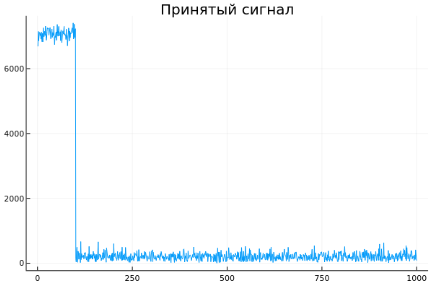
Based on the presented graphs:
-
The upper graph shows the transmitted rectangular signal, which starts with an amplitude of about
1and it quickly drops to zero. This is a typical pulse-shaped signal corresponding to the square wave parameters set for the transmitter. -
The lower graph shows the received signal, which contains a noise component. You can see that at the beginning of the signal (up to approximately
250There is a noticeable amplitude level, and then it decreases and becomes more noisy. This is typical for the received signal, where due to the effects of noise and attenuation of the signal, its amplitude decreases and the basic information becomes less pronounced.
The graphs demonstrate that a system based on system objects successfully performs its functions in modeling a radar signal. System objects allow you to implement the main stages — generation, transmission, reception and addition of noise — at the block level, without having to dive into the details of modeling using the blocks of the Engee library.
Common methods of system objects
System objects in Engee offer a number of common methods that simplify the management and configuration of their behavior. Below is a description of each of them.
step!
Method step! runs the main logic or algorithm associated with the system object. It is used to perform calculations or data processing based on the current state of the object. For example, in a radar system, a call step! for the signal generator, it starts the process of generating the next pulse.:
# Pulse generation
signal = step!(waveform)

# Signal transmission and reception
transmitted = step!(transmitter, signal)
received = step!(receiver, transmitted)
Here is the method step! sequentially starts each component: a waveform generator, a transmitter and a receiver, ensuring that the signal passes through the entire system. Every challenge step! performs one iteration of data processing.
release!
After the system object has been configured and used, some of its properties may be blocked. Method release! allows you to unlock an object and change its properties if you need to reconfigure its parameters. This method is useful when it is necessary to make changes to an already configured object, for example, to change the power of the transmitter or the frequency of the generator, without creating a new object. Using release! frees the object to add new values to its parameters. For example:
release!(waveform) # Allowing changes to the signal generator object

waveform.SampleRate = 2e6       # Changing the sampling frequency by 2 MHz

release!(transmitter) # Allowing changes to the transmitter object

transmitter.Gain = 45           # Gain change by 45 dB
In this example, the method release! allows you to make changes to existing objects. waveform and transmitter without creating them anew. This is useful if the system parameters need to be adjusted to other operating conditions.
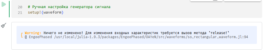
setup!
Method setup! performs one-time actions necessary for the initial configuration of the system object. It prepares the object for operation, for example, checks the correctness of the set parameters and allocates the necessary resources.
Method setup! It is called automatically at the first start. step!, but it can be called manually to check the readiness of the object in advance and make sure that its settings are correct.
This method is useful for the model preparation stage, when it is important to make sure that all objects are configured correctly before starting the main processing. For example:
setup!(waveform)|
The default method is
Therefore, you must first unlock the object for changes and then call |