EngeePhased.MFSKWaveform
Continuous signal generator with multi-position frequency modulation.
| Library |
|
| Block |
Description
A continuous signal with multi-position frequency modulation (FM) is used in automotive radars to improve simultaneous pulse and Doppler detection of the distance to multiple targets. System object EngeePhased.MFSKWaveform generates a continuous signal with a multi-position FM. A multi-position FM signal consists of two alternating sequences of increasing frequencies, as described in the Algorithms section.
To generate a continuous signal with a multi-position FM, follow these steps:
-
Create an object EngeePhased.MFSKWaveform and set its properties.
-
Call the object with arguments as if it were a function.
To learn more about how to work with system objects, see Engee System Objects.
Syntax
Creation
-
waveform = EngeePhased.MFSKWaveform()— creates a system objectwaveforma multi-position FM signal generator. -
waveform = EngeePhased.MFSKWaveform(Name=Value)— creates a system objectwaveforma multi-position FM signal generator with the specified property"Name", set to the specified valueValue. You can specify additional properties as name-value pairs in any order (Name1=Value1,…,NameN=ValueN).
Arguments
Output arguments
Y — multi-position FM signal
+
the complex vector
Details
An output signal with a multi-position FM, returned as a complex vector of size . When is the method step! When it reaches the end of the signal, the output samples loop from the beginning of the signal, forming a periodic signal.
| Типы данных |
|
| Support for complex numbers |
yes |
Features
#
StepTime —
frequency step duration
Real number
Details
The duration of each frequency step in seconds, given as a positive scalar.
By default — 1e−4.
#
StepsPerSweep —
total number of frequency deviation steps
Real number
Details
The total number of frequency deviation steps specified as an even positive integer.
By default — 64.
#
SampleRate —
sampling rate of the output signal
Real number
Details
The sampling frequency of the signal in the form of a positive scalar. Units of measurement — Hz.
By default — 1e6.
#
NumSteps —
the number of frequency steps in the signal
Real number
Details
The number of frequency steps in the output signal, specified as a positive integer.
By default — 1.
#
NumSamples —
the number of samples in the signal
Real number
Details
The number of samples in the output signal, specified as a positive integer.
By default — 1.
#
OutputFormat —
Output format
String
Details
Output format:
-
"Steps"(by default) — the output signal consists of all samples contained in the whole number of frequency steps NumSteps. -
"Samples"— the output signal consists of an integer number of samples [Property:numSamples]. -
"Sweeps"— the output signal consists of all samples contained in the whole number of frequency deviation steps NumSweeps.
The values of OutputFormat do not affect the properties of the signal.
#
NumSweeps —
the number of frequency deviation steps in the signal
Real number
Details
The number of frequency deviation steps in the output signal, specified as a positive integer.
By default — 1.
#
FrequencyOffset —
frequency offset
Real number
Details
The frequency offset specified as a real scalar. The frequency offset defines the frequency shift between two sequences. Units of measurement — Hz.
By default — 1000.
#
SweepBandwidth —
frequency deviation
Real number
Details
Frequency deviation in the output signal, specified as a positive scalar. Units of measurement — Hz.
The signal frequency deviation is the difference between the highest and lowest frequencies of any of the sequences.
By default — 1e5.
Methods
Examples
Generation of signals with multi-position frequency modulation
Details
We will generate a signal with a multi-position frequency modulation with a sampling frequency 10 MHz, the duration of the step 5 iss, number of steps 6, frequency offset 400 kHz and signal band 4 MHz.
Initialize the parameters.
fs = 10e6                # Частота дискретизации (Гц)
tstep = 5e-6             # Длительность одного шага (с)
stepsPerSweep = 6        # Общее число ступеней перестройки частоты
freqOffset = 400e3       # Смещение частоты (Гц)
sweepBW = 4e6            # Полоса перестройки (Гц)

# Дополнительные параметры
PRF = 1 / (stepsPerSweep * tstep);   # Частота повторения
sweeps2plot = 1;
Let’s use EngeePhased.MFSKWaveform to create a probe signal system object mfsk_wav.
mfsk_wav = EngeePhased.MFSKWaveform(
    SampleRate = fs,
    StepTime = tstep,
    StepsPerSweep = stepsPerSweep,
    SweepBandwidth = sweepBW,
    FrequencyOffset = freqOffset,
    OutputFormat = "Sweeps",
    NumSweeps = sweeps2plot
);
Making a call to the system object EngeePhased.MFSKWaveform using the mfsk_wav variable.
mfsk_signal = mfsk_wav();Using the function plot Let’s construct an oscilloscope in the form of an IQ component, a module, and a phase of the signal.
# построение IQ-компонент
t_grid = range(start = 0,step = 1/fs,length = length(mfsk_signal)) * 1e6 # сетка времени, мкс
fig1 = plot(t_grid,real.(mfsk_signal),title = "синфазная составляющая",lab="",ylab="Амплитуда")
fig2 = plot(t_grid,imag.(mfsk_signal),title = "квадратурная составляющая",lab="",xlab = "Время, мкс",ylab="Амплитуда");

plot(fig1,fig2,layout = (2,1))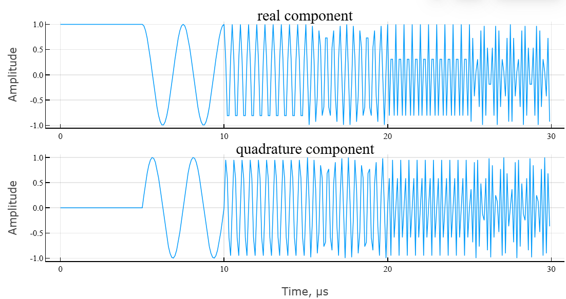
# построение модуля и фазы сигнала
fig3 = plot(t_grid,abs.(mfsk_signal),title = "Модуль комплексного сигнала",lab="",ylab="Амплитуда");
fig4 = plot(t_grid,angle.(mfsk_signal)*180/pi,title = "Аргумент комплексного сигнала",lab="",xlab = "Время, мкс",ylab="Фаза, град.");

plot(fig3,fig4,layout = (2,1))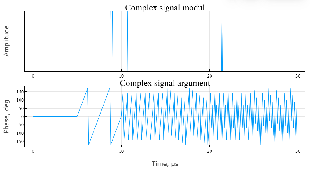
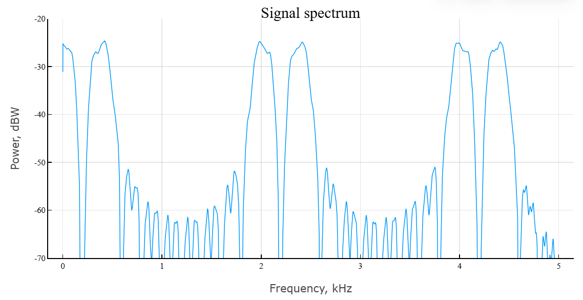
The main characteristic of the signal is the frequency spectrum and the spectrogram. Let’s use the built-in function periodogram.
# расчет спектра сигнала
spec_MFSK,f = EngeePhased.Functions.periodogram(
    mfsk_signal, # исходный сигнал
    ones(size(mfsk_signal)...),
    8192; # длина частоты дискретизации
    out = :data, # тип выхода
    fs = fs, # частота дискретизации
    spectrumtype = "power" # тип спектра
);
Visualize the result using the function plot.
plot(
    f * 1e-6,
    EngeePhased.Functions.mag2db.(spec_MFSK),
    lab="", xlab = "Частота, МГц",
    ylab = "Мощность, дБВт",
    title = "Спектр сигнала",
    ylim = (-70,-20)
)
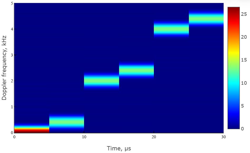
To calculate the spectrogram, we use the built-in function spectrogram.
# расчет спектрограммы
spectgm_cfm,f1,t1 = EngeeDSP.Functions.spectrogram(
    real.(mfsk_signal);
    nfft = 512, # длина БПФ
    window = round(Int,length(mfsk_signal)/stepsPerSweep),
    noverlap = 0, # перекрытие окна
    spectrumtype = "power", # тип спектра — по мощности
    freqrange = "onesided", # диапазон спектра — односторонний
    out = :data, # тип выхода — массив данных
    fs = fs # частота дискретизации
);
We visualize the result of the spectrogram calculation using the function heatmap.
# построение спектрограммы
heatmap(
    t1[:]*1e6,
    f1[:]*1e-6,
    abs.(spectgm_cfm),color = :jet,
    xlab = "Время, мкс",
    ylab = "Частота Доплера, МГц"
)
Algorithms
A signal with multi-position frequency modulation is formed by switching the carrier frequency in accordance with a given multi-level digital code:
where
-
— the duration of one character;
-
— the meaning of an information symbol from a multi-position alphabet;
-
— frequency spacing between positions.
To generate a stepwise frequency modulated signal, the following parameters must be set:
-
filter sampling rate ;
-
pulse duration ;
-
pulse repetition rate ;
-
number of pulses ;
-
number of frequency steps ;
-
the initial frequency of the signal ;
-
frequency spacing between positions ;
-
the final frequency of the signal ;
-
frequency deviation .

Each sequence is a set of continuous signals, increasing in frequency. Offset the difference between the two sequences is constant and can be positive or negative. The complete signal consists of an even number of steps the same duration . Then each sequence consists of steps. Signal frequency deviation is the difference between the highest and lowest frequencies of any of the sequences. Meaning it is always positive, which indicates an increase in frequency. The frequency difference between the successive steps of each sequence is determined as follows:
The lowest frequency of the first sequence is always 0 Hz and corresponds to the carrier frequency of the bandpass signal. The lowest frequency of the second sequence can be positive or negative and is equal to . Negative frequencies correspond to the frequencies of the bandpass signal that are lower than the carrier frequency. The duration of the signal is set to . The properties of the system object corresponding to the signal parameters are shown in the table.
| Signal Parameter | Property |
|---|---|
|
|
|
|
|
|
|
Literature
-
Meinecke, Marc-Michael, and Hermann Rohling, Combination of LFMCW and FSK Modulation Principles for Automotive Radar Systems. German Radar Symposium GRS2000. 2000.
-
Rohling, Hermann, and Marc-Michael Meinecke. Waveform Design Principles for Automotive Radar Systems. CIE International Conference on Radar. 2001.