EngeePhased.SteppedFMWaveform
A signal generator with stepwise frequency modulation.
| Library |
|
| Block |
Description
System object EngeePhased.SteppedFMWaveform It is a stepwise frequency modulated (FM) signal generator.
To generate a step-by-step FM signal, follow these steps:
-
Create an object EngeePhased.SteppedFMWaveform and set its properties.
-
Call the object with arguments as if it were a function.
To learn more about how to work with system objects, see Engee System Objects.
Syntax
Creation
-
waveform = EngeePhased.SteppedFMWaveform()— creates a system objectwaveforma stepwise FM signal with default properties. -
waveform = EngeePhased.SteppedFMWaveform(Name=Value)— creates a system objectwaveforma stepwise FM signal generator with specified properties in the form of a pairName=Value, whereName— the name of the property, andValue— the appropriate value. You can specify multiple pairs «name-value» the order of the pairs does not matter. Unspecified properties retain their default values.
Using
-
Y = waveform()— returns pulse counts with a stepwise FM in the form of a column vector Y. The output signal Y is obtained by increasing the frequency of the previous output signal by the amount specified by the property FrequencyStep. -
Y = waveform(prfidx)— uses the prfidx index to select the pulse repetition rate (PRF) from a predefined vector of values set by the PRF property. This syntax applies if the PRFOutputPort property is set totrue. -
Y = waveform(freqoffset)— uses freqoffset to generate a frequency offset signal. Use this syntax in cases where it is necessary to dynamically update the frequency of transmitted pulses. This syntax applies if for the property FrequencyOffsetSource value set"Input port". -
Y,prf = waveform(_)— also returns the current pulse repetition rate prf. To use this syntax, set the PRFOutputPort property totrue, and for the property OutputFormat value"Pulses". -
Y,coeff = waveform(_)— also returns the coefficients of the matched coeff filter for the current pulse. To use this syntax, set the [Property:CoordicientsOutputPort] valuetrue.
You can combine optional input and output arguments if properties are specified that include them. Optional inputs and outputs must be listed in the same order as the properties that include them. For example, Y,prf,coeff = waveform(prfidx,freqoffset).
Arguments
Input arguments
prfidx — pulse repetition rate index
+
a positive integer
Details
Pulse Repetition rate index (PRF), set as a positive integer.
Dependencies
To use this argument, set the PRFOutputPort property to true.
freqoffset — frequency offset, Hz
+
scalar
Details
The frequency offset specified as a scalar.
Dependencies
To use this argument, set the property to FrequencyOffsetSource value "Input port".
| Типы данных |
|
Output arguments
Y — pulse signal
+
column vector
Details
The output signal returned as a column vector.
| Типы данных |
|
prf —
pulse repetition
rate
scalar
Details
The current pulse repetition rate in Hz, returned as a scalar.
Dependencies
To use this argument, set the PRFOutputPort property to true, and for the property OutputFormat value "Pulses".
| Типы данных |
|
| Support for complex numbers |
yes |
coeff — coefficients of the matched filter
+
vector | the matrix
Details
Coefficients of the matched filter returned as a complex vector of size or a complex matrix of size .
Dependencies
To use this argument, set the property to [Property:CoordicientsOutputPort] value true.
| Типы данных |
|
| Support for complex numbers |
yes |
Features
#
FrequencyStep —
the size of the linear step in frequency
Real number
Details
The size of the linear frequency step, set as a positive scalar. The units of measurement are Hz.
Default value — 20e3.
#
NumSteps —
the number of frequency steps in a pulse
Integer
Details
The number of frequency steps specified as a positive integer.
Default value — 5.
#
NumSamples —
number of samples of the output signal
Integer
Details
The number of samples of the output signal, set as a positive integer.
Default value — 100.
Dependencies
To use this property, set the OutputFormat value "Samples".
#
OutputFormat —
output signal format
String
Details
The format of the output signal in the form "Pulses" (by default) or "Samples":
-
If you set this property to
"Pulses", then the output of the block consists of several pulses. The number of pulses is the value of the property NumPulses. -
If you set this property to
"Samples", then the output of the block consists of several samples. The number of samples is the value of the [Property:numSamples] property.
#
FrequencyOffsetSource —
The source of the frequency offset setting
String
Details
The source of the frequency offset setting, set as "Property" (by default) or "Input port":
-
If the value is set to
"Property", then the offset is determined by the value of the FrequencyOffset. -
If the value is set to
"Input port", the offset is determined by the value of the freqoffset argument.
#
NumPulses —
number of output signal pulses
Integer
Details
The number of pulses of the output signal, set as a positive integer.
Default value — 1.
Dependencies
To use this property, set the OutputFormat value "Pulses".
#
PRF —
pulse repetition rate
Real number
Details
Pulse repetition rate (PRF), set as a scalar or string vector. The units of measurement are Hz. The pulse repetition period (PRI) is the inverse of the pulse repetition rate (PRF). The PRF value must satisfy the following constraints:
-
The product of PRF and PulseWidth must be less than or equal to one. This condition requires that the pulse width be less than one PRI. For a phase-coded signal, the pulse duration is equal to the product of the duration of one chip and the number of chips.
-
Relation SampleRate k PRF must be an integer. This condition requires that the number of samples in one PRI be an integer.
The PRF value can be set using only the values of the PRF property or the values of the property in combination with the input argument prfidx.
-
If PRFOutputPort has a value
false, PRF is set only using the PRF properties. You can:-
Implement a constant PRF by specifying the PRF property as a positive real scalar value.
-
Implement a discrete PRF by specifying the PRF property as a vector string with positive real elements. Each object call uses consecutive elements of this vector as a PRF. As soon as the object reaches the last element of the vector, it cyclically continues the process with the first element of the vector.
-
-
When PRFOutputPort has a value
trueyou can set the value of PRF using the PRF property in combination with the input argument prfidx. You implement a selectable PRF by specifying the PRF property as a vector string with positive real elements. When executing an object, the PRF is selected using the index specified in the input argument prfidx to index the PRF vector.
In all cases, the number of output samples is fixed if you set the OutputFormat value "Samples". When using a variable pulse repetition rate (PRF) and setting for the property OutputFormat values "Pulses" the number of counts may vary.
Default value — 10e3.
#
CoefficientsOutputPort —
enable output of matched filter coefficients
Logical
Details
Enable or disable the output of the coefficients of the matched filter by specifying the value false (by default) or true. Set this property to true to enable the output of matched filter coefficients for the waveform used during the simulation.
#
PulseWidth —
pulse duration
Real number
Details
The pulse duration, set as a positive scalar. The value must meet the condition PulseWidth < 1/PRF. The units of measurement are seconds.
Default value — 50e−6.
Dependencies
To use this property, set the DurationSpecification property to "Pulse width".
#
SampleRate —
sampling rate
Real number
Details
The sampling frequency of the signal, set as a positive scalar. The units of measurement are Hz.
Default value — 100e3.
#
DurationSpecification —
pulse duration specification
String
Details
The method of setting the pulse duration in the form "Pulse width" (by default):
-
"Pulse width"— the pulse duration is set using the PulseWidth property.
#
PRFOutputPort —
enable PRF output
Logical
Details
If you set the value for this property true, you can pass an index argument to an object to select a predefined value from a vector of property values PRF. If you set the value for this property false (by default), the object will use the PRF property to define the PRF sequence used in the simulation.
#
FrequencyOffset —
frequency offset
Real number
Details
The frequency offset specified as a scalar. The unit of measurement is Hz.
Default value — 0.
Dependencies
To use this property, set the FrequencyOffsetSource value "Property".
Methods
Examples
Generation of signals with stepwise frequency modulation
Details
We will generate a stepwise frequency modulation signal with a sampling frequency 10 MHz, the duration of the step 5 iss, the number of steps 4 and the signal band 5 MHz.
Initialize the parameters.
fs = 10e6 # Частота дискретизации (Гц)
pulseWidth = 5e-6; # Длительность одного импульса (с)
numSteps = 4 # Общее число шагов частоты
freqStep = 5e6 / numSteps; # Шаг частоты (Гц) – полная полоса 5 МГц
freqOffset = 0 # Смещение частоты (Гц)

# Единая частота повторения для всех сигналов
PRF = round(1/(2*pulseWidth)); # Гц
numSweeps = 4; # Количество чипов для отображения
Let’s use EngeePhased.SteppedFMWaveform to create a probe signal system object sfm_waveform.
sfm_waveform = EngeePhased.SteppedFMWaveform(
    SampleRate = fs,
    PulseWidth = pulseWidth,
    PRF = PRF,
    NumSteps = numSteps,
    FrequencyStep = freqStep,
    FrequencyOffset = freqOffset,
    OutputFormat = "Pulses",
    NumPulses = numSweeps
);
Making a call to the system object EngeePhased.SteppedFMWaveform using the sfm_signal variable.
sfm_signal = sfm_waveform();Using the function plot Let’s construct an oscilloscope in the form of an IQ component, a module, and a phase of the signal.
# построение IQ-компонент
t_grid = range(start = 0,step = 1/fs,length = length(sfm_signal)) * 1e6 # сетка времени, мкс
fig1 = plot(t_grid,real.(sfm_signal),title = "синфазная составляющая",lab="",ylab="Амплитуда")
fig2 = plot(t_grid,imag.(sfm_signal),title = "квадратурная составляющая",lab="",xlab = "Время, мкс",ylab="Амплитуда");

plot(fig1,fig2,layout = (2,1))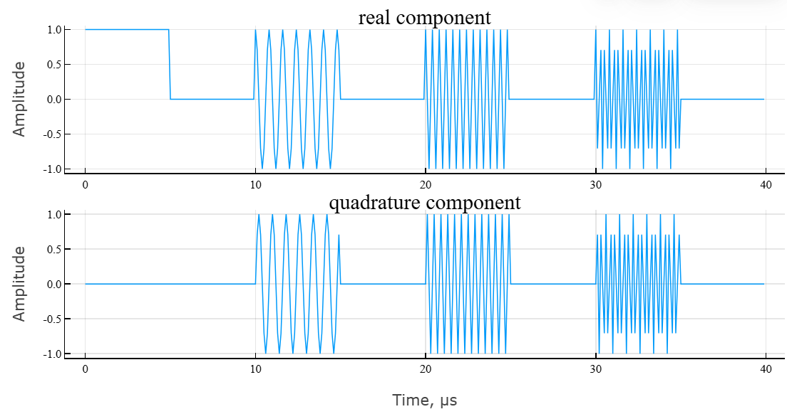
# построение модуля и фазы сигнала
fig3 = plot(t_grid,abs.(sfm_signal),title = "Модуль комплексного сигнала",lab="",ylab="Амплитуда");
fig4 = plot(t_grid,angle.(sfm_signal)*180/pi,title = "Аргумент комплексного сигнала",lab="",xlab = "Время, мкс",ylab="Фаза, град.");

plot(fig3,fig4,layout = (2,1))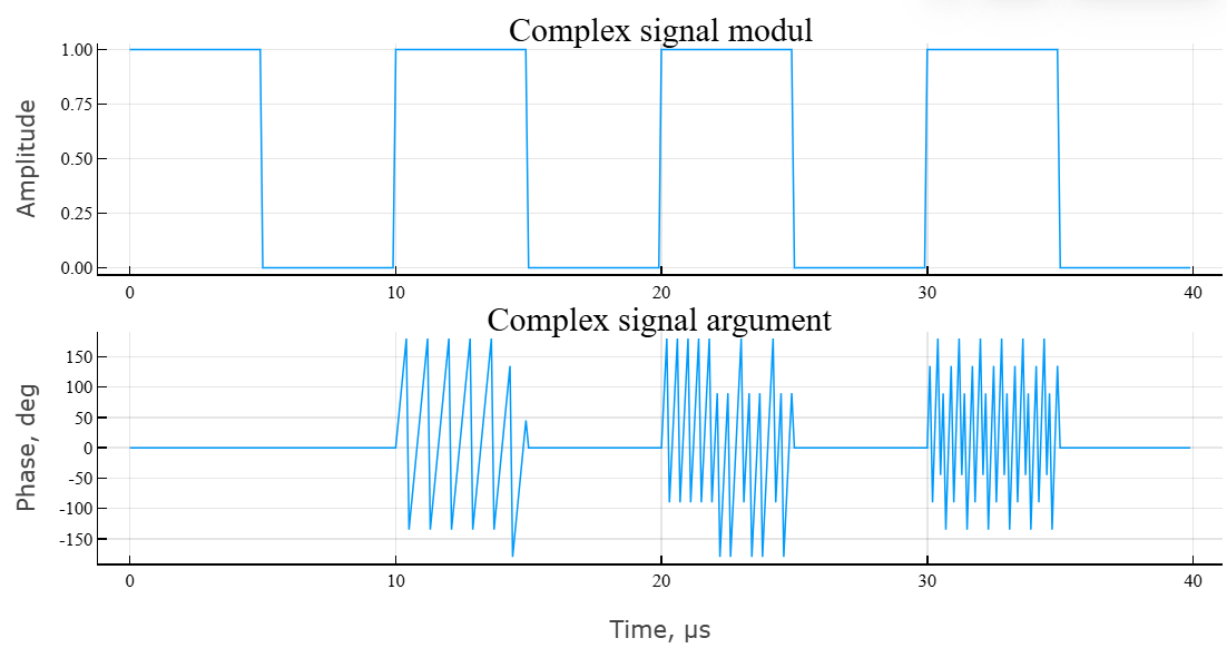
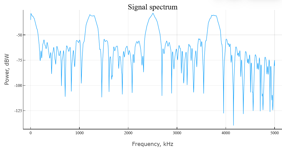
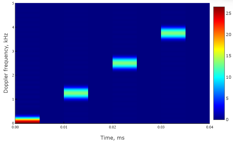
The main characteristic of the signal is the frequency spectrum and the spectrogram. Let’s use the built-in function periodogram.
# расчет спектра сигнала
spec_CFM,f = EngeePhased.Functions.periodogram(
    sfm_signal, # исходный сигнал
    ones(size(sfm_signal)...),
    8192; # длина частоты дискретизации
    out = :data, # тип выхода
    fs = fs, # частота дискретизации
    spectrumtype = "power" # тип спектра
);
Visualize the result using the function plot.
plot(
    f * 1e-3,
    EngeePhased.Functions.mag2db.(spec_CFM),
    lab="", xlab = "Частота, кГц",
    ylab = "Мощность, дБВт",
    title = "Спектр сигнала"
)
To calculate the spectrogram, we use the built-in function spectrogram.
# расчет спектрограммы
spectgm_cfm,f1,t1 = EngeeDSP.Functions.spectrogram(
    real.(sfm_signal);
    nfft = 1024, # длина БПФ
    window = 50,
    noverlap = 0, # перекрытие окна
    spectrumtype = "power", # тип спектра — по мощности
    freqrange = "onesided", # диапазон спектра — односторонний
    out = :data, # тип выхода — массив данных
    fs = fs # частота дискретизации
);
We visualize the result of the spectrogram calculation using the function heatmap.
# построение спектрограммы
heatmap(
    t1[:]*1e3,
    f1[:]*1e-6,
    abs.(spectgm_cfm),color = :jet,
    xlab = "Время, мс",
    ylab = "Частота Доплера, МГц",
)
Algorithms
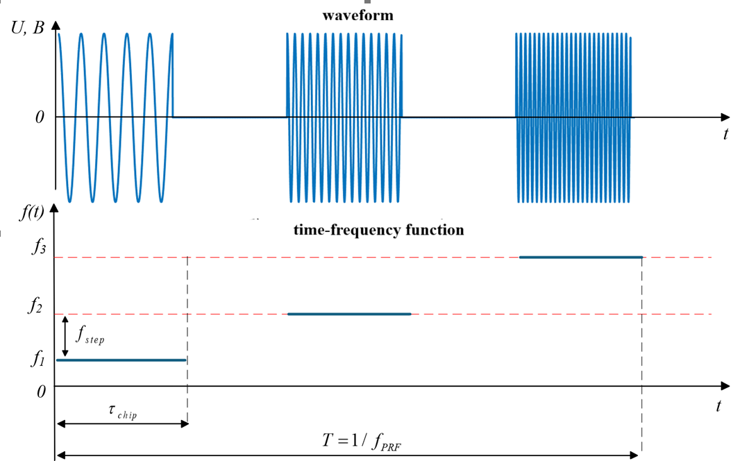
A stepwise frequency modulated signal is a sequence of pulses, the frequency of which varies from pulse to pulse in discrete steps.:
where
-
— signal amplitude;
-
— frequency change period;
-
— the magnitude of the frequency step (steps);
-
— number of frequency steps;
-
— initial frequency;
-
— pulse duration at one stage;
-
— defines a rectangular envelope:
To generate a stepwise frequency modulated signal, the following parameters must be set:
-
filter sampling rate ;
-
pulse duration ;
-
pulse repetition rate ;
-
number of pulses ;
-
the initial frequency of the signal ;
-
the final frequency of the signal ;
-
frequency deviation .