Комбинирование слоев
В этой демонстрации показано, как можно реализовать послойную альфа-композицию с помощью 10 строк кода с использованием OffsetArrays и PaddedViews. Если вам нужны более строго организованные средства, ColorBlendModes предоставляет определения и операции композиции для режимов наложения.
using Images
using OffsetArrays # предоставляем `OffsetArray`
1. Базовая операция смещения и дополнения
Предположим, у нас есть два объекта прозрачного цвета и мы хотим разместить их на холсте с частичным перекрытием.
red_patch = fill(RGBA(1., 0., 0., 1), 24, 24)
green_patch = fill(RGBA(0., 1., 0., 1), 32, 32)
mosaicview(red_patch, green_patch; npad=20, nrow=1, fillvalue=colorant"white")
Предположим, что оси холста начинаются с (1, 1); здесь мы оставляем красный участок без смещения, а зеленый участок смещаем на 6 пикселей вниз и на 16 пикселей вправо, после чего выполняем их дополнение до общих осей.
green_o = OffsetArray(green_patch, 6, 16)
r, g = paddedviews(Gray(0.2), red_patch, green_o)
mosaicview(r, g; npad=20, nrow=1, fillvalue=colorant"white")
Обратите внимание, что их оси и размеры изменились после смещения и дополнения:
# Независимо от особенностей реализации `Base.OneTo(32)` практически эквивалентно `1:32`
println("before shifting -- size: ", size(green_patch), " axes: ", axes(green_patch))
println("after shifting  -- size: ", size(green_o), " axes: ", axes(green_o))
println("after padding   -- size: ", size(g), " axes: ", axes(g))
before shifting -- size: (32, 32) axes: (Base.OneTo(32), Base.OneTo(32))
after shifting -- size: (32, 32) axes: (OffsetArrays.IdOffsetRange(values=7:38, indices=7:38), OffsetArrays.IdOffsetRange(values=17:48, indices=17:48))
after padding -- size: (38, 48) axes: (Base.IdentityUnitRange(1:38), Base.IdentityUnitRange(1:48))Оси после дополнения сохраняются, а значит, исходное изображение можно легко получить из результатов дополнения следующим образом:
r[axes(red_patch)...]
g[axes(green_o)...]
Как описано в этой статье, существует несколько методов комбинирования:
# операция сложения
out_add = r .+ g

# операция очистки
out_clear = copy(r)
out_clear[axes(green_o)...] .= colorant"black"

# операция умножения
out_mul = copy(r)
# поканальное умножение
channelview(out_mul)[:, axes(green_o)...] .*= channelview(green_o)

# операция перекрытия
out_over = copy(r)
out_over[axes(green_o)...] .= green_o

# отображаем результаты этих операций
mosaicview(out_add, out_clear, out_mul, out_over;
           npad=20, nrow=1, fillvalue=colorant"white")
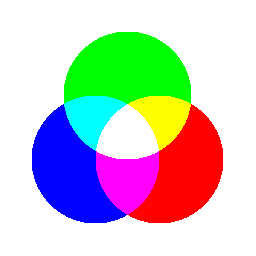
2. Построение панели трех основных цветов
Теперь давайте воспользуемся тем же приемом, чтобы создать что-то более осмысленное. Сначала создадим три круга красного, зеленого и синего цветов.
using ImageDraw
function make_circle(sz, c::T) where T
    # заполняем прозрачным цветом, чтобы устранить черную область
    fillvalue = ARGB(c)
    img = fill(ARGB{eltype(T)}(0., 0., 0., 0.), sz...)
    origin = sz .÷ 2
    r = sz .÷ 4
    draw!(img, Ellipse(origin..., r...), fillvalue)
    img
end

# создаем три круга красного, зеленого и синего цветов
red_c   = make_circle((256, 256), ARGB(1., 0., 0., 1.))
green_c = make_circle((256, 256), ARGB(0., 1., 0., 1.))
blue_c  = make_circle((256, 256), ARGB(0., 0., 1., 1.))

mosaicview(red_c, green_c, blue_c; nrow=1)
Затем сместим эти круги в соответствующие позиции, дополним их до общих осей и, наконец, скомбинируем с помощью операции сложения:
r = size(red_c, 1) ÷ 8
red_o   = OffsetArray(red_c,    r,  r)
green_o = OffsetArray(green_c, -r,  0)
blue_o  = OffsetArray(blue_c,   r, -r)

color_panel = sum(paddedviews(zero(eltype(red_o)), red_o, green_o, blue_o))
color_panel = color_panel[axes(red_c)...] # обрезаем пустую область
Эта страница была создана с помощью DemoCards.jl и Literate.jl.