Comparator
The behavioral model of the comparator integrated circuit.
blockType: AcausalElectricPowerSystems.IntegratedCircuits.Comparator
|
Path in the library: |

Description
Block Comparator It is an abstract behavioral model of a comparator integrated circuit. It does not model the internal implementation at the transistor level. Therefore, the block is executed quickly during the simulation, while maintaining the correct behavior of the inputs and outputs. The block models differential inputs from the point of view of electrical engineering as having infinite resistance and finite or zero capacitance.
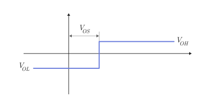
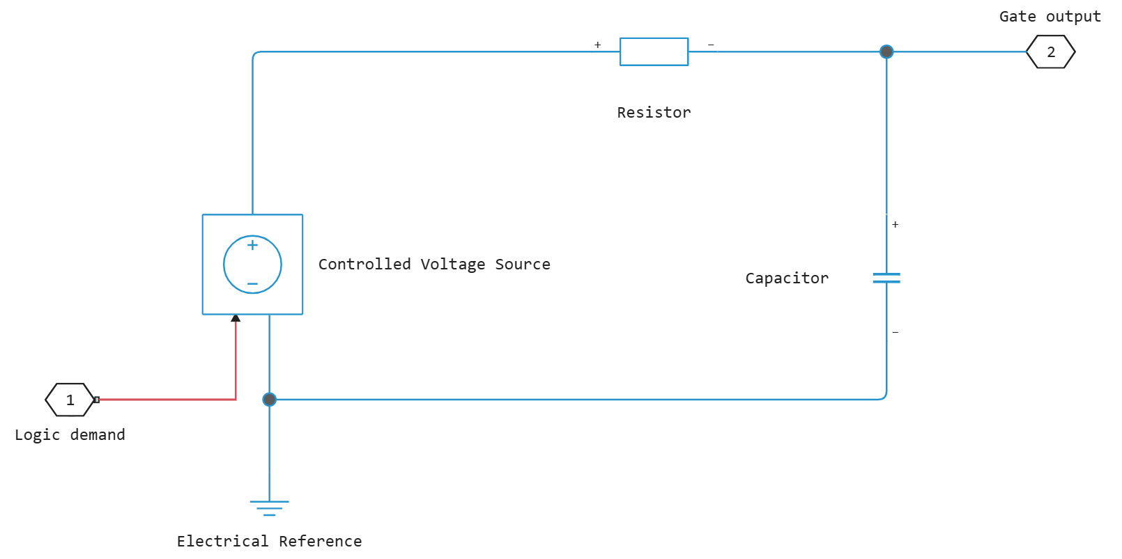
The block simulates a logical output signal as a voltage source controlling a series-connected resistor and a capacitor connected to ground. The output contact is connected to the junction of the resistor and capacitor. If the input voltage difference exceeds the threshold input voltage, the output signal is equal to the value of the parameter High level output voltage ( ). Otherwise, the output signal is equal to the value of the parameter Low level output voltage ( ).
The output model is shown in the following figure.
Assumptions and limitations
The simulation of the output signal in the form of a controlled voltage source corresponds to the output push-pull cascade (totem-pole) or cascade type «push pull» (push-pull). For modeling an open collector device:
-
Connect the output pin to the base of the unit NPN Bipolar Transistor or PNP Bipolar Transistor.
-
Set for the parameter Output resistance the appropriate value.
Ports
Conserving
#
+
—
non-inverting input
electricity
Details
A non-directional port connected to a non-inverting comparator input.
| Program usage name |
|
#
−
—
inverting input
electricity
Details
A non-directional port connected to the inverting input of the comparator.
| Program usage name |
|
#
OUT
—
Output port
electricity
Details
An undirected port connected to the comparator output.
| Program usage name |
|
Parameters
Outputs
#
Propagation delay —
propagation delay
s | ns | us | ms | min | hr | d
Details
Set this value taking into account the delays in signal propagation from high to low and from low to high.
| Units |
|
| Default value |
|
| Program usage name |
|
| Evaluatable |
Yes |
#
Output resistance —
output resistance
Ohm | mOhm | kOhm | MOhm | GOhm
Details
The ratio of the output voltage drop to the output current. Set this parameter to , where — reduced output high voltage at output current .
| Units |
|
| Default value |
|
| Program usage name |
|
| Evaluatable |
Yes |
#
Low level output voltage —
low-level output voltage
V | uV | mV | kV | MV
Details
Steady-state output voltage when the voltage difference at the inputs is less than or equal to the threshold voltage, and the output current is zero.
| Units |
|
| Default value |
|
| Program usage name |
|
| Evaluatable |
Yes |
#
High level output voltage —
high-level output voltage
V | uV | mV | kV | MV
Details
Steady-state output voltage when the voltage difference at the inputs exceeds the threshold voltage and the output current is zero.
| Units |
|
| Default value |
|
| Program usage name |
|
| Evaluatable |
Yes |
Inputs
#
Average input capacitance —
average input capacity
F | pF | nF | uF | mF
Details
Usually, the capacity value can be found in the manufacturer’s technical description. Setting this value to zero can reduce the simulation time.
| Units |
|
| Default value |
|
| Program usage name |
|
| Evaluatable |
Yes |
#
Input offset voltage —
input bias voltage
V | uV | mV | kV | MV
Details
The voltage that must exceed the input voltage difference in order for the comparator to produce a logical output signal 1.
| Units |
|
| Default value |
|
| Program usage name |
|
| Evaluatable |
Yes |