Timer
The behavioral model of the integrated circuit timer.
blockType: AcausalElectricPowerSystems.IntegratedCircuits.Timer
|
Path in the library: |
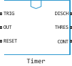
Description
Block Timer It is a behavioral model of a timer integrated circuit such as the NE555.
The following figure shows the block implementation structure:
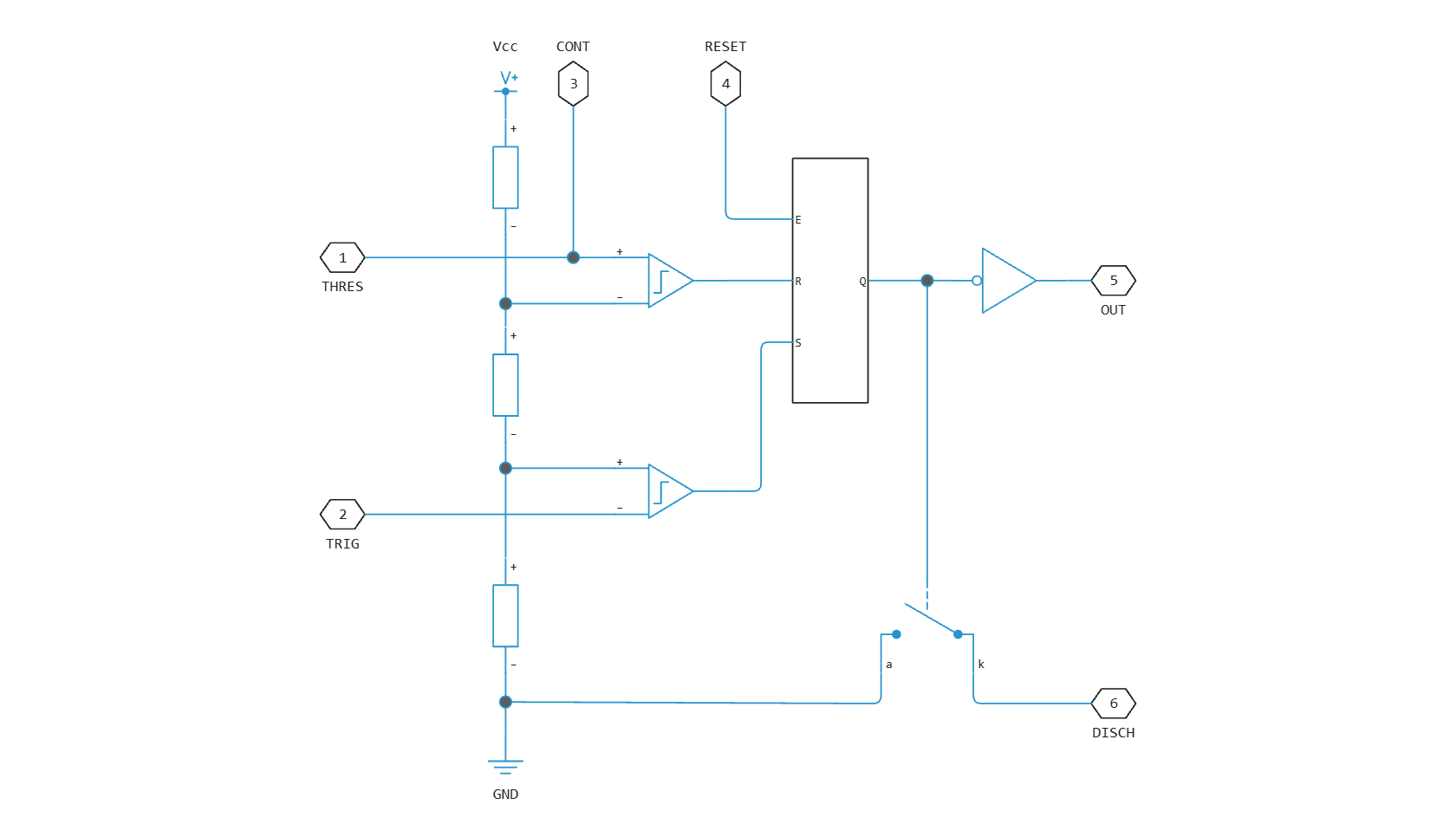
Parameter Potential divider component resistance sets the values of the three resistors forming the voltage divider. The two comparator inputs have infinite input impedance and zero input capacitance. Block S-R Latch provides latch functionality with installation and reset. It includes an output capacitor and a resistor with values set according to the parameter value Propagation delay. The block simulates the output stage inverter using the block CMOS NOT. The output resistance, low-level output voltage and high-level output voltage for the CMOS valve are set in the settings window of the unit Timer. The element switch approximates a bipolar NPN transistor on a real timer as a switch with preset resistance values when switched on and off directly.
Assumptions and limitations
-
Behavior is described abstractly. The results are not as accurate as when using a transistor-level model.
-
The delay in response to a change in the input signals depends solely on the time constant of the RC resistor-capacitor circuit at the latch output. In practice, the delay has a more complex dependence on the structure of the device. Set this value based on the rise and fall time of the output pulse.
-
The output voltage drop is a linear function of the output current. In practice, this ratio corresponds to a push-pull pair of bipolar transistors.
-
The controlled switch circuit used in the unit is an approximation to the open collector circuit.
-
The power supply is connected inside the component, and it is assumed that the GND pin is grounded.
Ports
Conserving
#
DISCH
—
discharge contact
electricity
Details
An undirected port connected to the timer’s discharge pin.
| Program usage name |
|
#
TRIG
—
launch contact
electricity
Details
The non-directional port associated with the timer start pin.
| Program usage name |
|
#
RESET
—
reset contact
electricity
Details
The non-directional port associated with the timer reset pin.
| Program usage name |
|
#
OUT
—
output contact
electricity
Details
An undirected port connected to the timer output pin.
| Program usage name |
|
#
CONT
—
managing contact
electricity
Details
An undirected port connected to the timer control pin.
| Program usage name |
|
#
THRES
—
threshold contact
electricity
Details
An undirected port connected to the timer’s threshold pin.
| Program usage name |
|
Parameters
Potential Divider
#
Potential divider component resistance —
resistance of the voltage divider component
Ohm | mOhm | kOhm | MOhm | GOhm
Details
A typical value for a type 555 timer is 5 Com. It can be measured directly between the positive power contact and the control contacts when the chip is not connected to the circuit.
| Units |
|
| Default value |
|
| Program usage name |
|
| Evaluatable |
Yes |
Discharge
#
Discharge switch off-resistance —
resistance of the element switch in the off state
Ohm | mOhm | kOhm | MOhm | GOhm
Details
A characteristic value is the leakage current of the discharge contact divided by the corresponding terminal voltage.
| Units |
|
| Default value |
|
| Program usage name |
|
| Evaluatable |
Yes |
#
Discharge switch on-resistance —
resistance of the element switch during direct switching
Ohm | mOhm | kOhm | MOhm | GOhm
Details
The characteristic value is the saturation voltage of the discharge contact divided by the corresponding current.
| Units |
|
| Default value |
|
| Program usage name |
|
| Evaluatable |
Yes |
Outputs
#
Propagation delay —
propagation delay
s | ns | us | ms | min | hr | d
Details
Set this value to the rise time of the input or output pulse.
| Units |
|
| Default value |
|
| Program usage name |
|
| Evaluatable |
Yes |
#
Output resistance —
output resistance
Ohm | mOhm | kOhm | MOhm | GOhm
Details
The ratio of the output voltage drop to the output current. Set this parameter to , where — reduced high-level output voltage at output current .
| Units |
|
| Default value |
|
| Program usage name |
|
| Evaluatable |
Yes |
#
Low level output voltage —
low-level output voltage
V | uV | mV | kV | MV
Details
Output voltage when the timer output signal is in a low state and no current is consumed at the output.
| Units |
|
| Default value |
|
| Program usage name |
|
| Evaluatable |
Yes |
#
High level output voltage —
high-level output voltage
V | uV | mV | kV | MV
Details
Output voltage when the timer output is in a high state and no current is being consumed.
| Units |
|
| Default value |
|
| Program usage name |
|
| Evaluatable |
Yes |
Supply
#
Power supply voltage —
Supply voltage
V | uV | mV | kV | MV
Details
Voltage value , which the block supplies internally to the timer component.
| Units |
|
| Default value |
|
| Program usage name |
|
| Evaluatable |
Yes |