Eddy Current (Physical Modeling Electrical Passive)
Eddy currents.
blockType: AcausalElectricPowerSystems.Passive.EddyCurrent
|
Path in the library: |

Description
Block Eddy Current simulates the effect of eddy currents by creating a magnetomotive force (MDS) that counteracts changes in the magnetic flux. In addition, the unit simulates parasitic effects using series resistance and parallel scattering resistance, as well as thermal effects using an additional thermal port. H.
Eddy currents in magnetic cores arise under the influence of time-varying magnetic fields. The changing flow induces an EMF in the material, causing a current in closed circuits. Such currents are usually undesirable and cause heating of the magnetic circuit.
This unit is used to add eddy current losses in the magnetic field to a custom transformer or other magnetic component.
Eddy current is sometimes called magnetic inductance because it is the magnetic analog of an electric inductor.
The equations
Equivalent magnetic circuit of the unit, including an eddy current circuit (bottom) and a parallel scattering circuit (top):
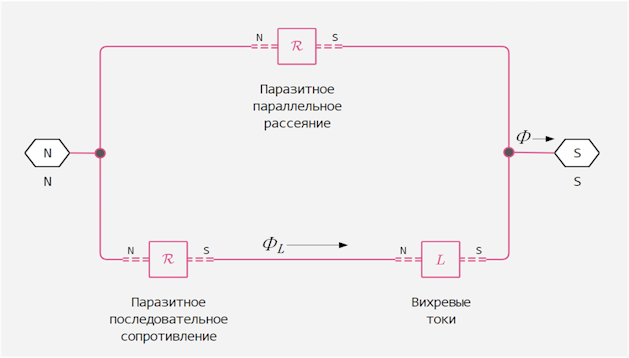
On the diagram:
-
— the total flow at the terminals. This flow consists of an eddy current flow and a parallel scattering flow.;
-
— flow through a loop of eddy currents.
The unit calculates the MDS of the terminals and the flow, Like:
where
-
— the conductivity of the eddy current circuit;
-
— parasitic series resistance of the eddy current circuit;
-
— parallel scattering.
Since the parasitic series resistance and parallel resistance have no losses, the total power dissipation in the unit is:
The relationship between electrical and magnetic transformer models
In the electrical field, eddy current losses are modeled using the parallel resistance of the primary winding. The equivalent circuit of an imperfect two-winding transformer:
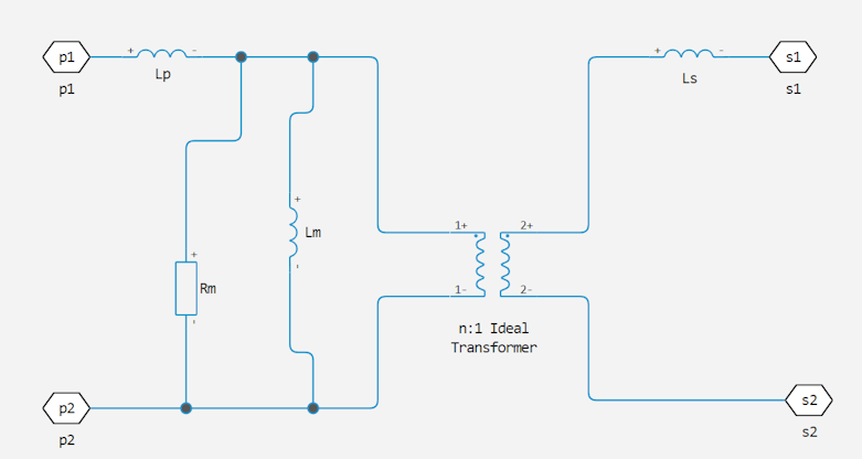
On the diagram:
-
and — the intrinsic inductance of the primary and secondary windings, respectively;
-
— mutual inductance of the two windings;
-
— the mutual resistance of the two windings due to eddy current losses.
This two-winding transformer can be similarly represented in the magnetic field. The equivalent scheme:
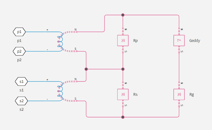
On the diagram:
-
and — the resistances associated with the primary and secondary windings, respectively;
-
— the resistance associated with the magnetic coupling of the two windings;
-
— the ratio of turns between the two windings.
Electric and magnetic circuits are equivalent if:
These relations can be used to calculate the equivalent properties of a two-winding transformer for one area based on the other.
Variables
Use the parameter group Initial Targets to set the priority and initial target values for the block parameter variables before modeling. For more information, see Configuring physical blocks using target values.
Ports
Conserving
#
N
—
The northern terminal
Magnetism
Details
The magnetic port corresponding to the northern terminal of the unit.
| Program usage name |
|
#
S
—
southern terminal
Magnetism
Details
The magnetic port corresponding to the southern terminal of the unit.
| Program usage name |
|
#
H
—
thermal port
warm
Details
Thermal port
Dependencies
To use this port, check the box Enable thermal port.
| Program usage name |
|
Parameters
Parameters
#
Conductance of eddy current loop —
eddy current loop conductivity
S | nS | uS | mS | 1/Ohm
Details
Eddy current loop conductivity, . This component is an analogue of magnetic inductance in the electrical field.
| Units |
|
| Default value |
|
| Program usage name |
|
| Evaluatable |
Yes |
#
Parasitic series reluctance —
consistent resistance
1/H | 1/mH | 1/nH | 1/uH
Details
Parasitic resistance eddy current circuits.
| Units |
|
| Default value |
|
| Program usage name |
|
| Evaluatable |
Yes |
#
Parasitic parallel permeance —
permeability of parallel scattering
H | nH | uH | mH
Details
Parasitic permeability parallel scattering contour. To facilitate the convergence of modeling in some circuit topologies, a small value of this parameter should be set.
| Units |
|
| Default value |
|
| Program usage name |
|
| Evaluatable |
Yes |
# Enable thermal port — visibility of the thermal port
Details
Select this option to enable the thermal port. H
| Default value |
|
| Program usage name |
|
| Evaluatable |
No |
#
Thermal mass —
heat capacity
J/K | kJ/K
Details
Heat capacity. This parameter controls the absorption and accumulation of thermal energy in the unit.
Dependencies
To use this option, check the box Enable thermal port.
| Units |
|
| Default value |
|
| Program usage name |
|
| Evaluatable |
Yes |