Heat Exchanger (TL)
Heat exchanger for systems with heat-conducting liquid flow and controlled flow.
blockType: EngeeFluids.HeatExchangers.EffectivenessNTU.ThermalLiquid
|
Path in the library: |

Description
Block Heat Exchanger (TL) simulates the cooling and heating of liquids through thermal conduction through a thin wall. The properties of a single-phase thermally conductive liquid are set on the tab Thermal Liquid. The second coolant is adjustable, and its properties are set only by the parameters on the tab Controlled Fluid. It does not get any properties from the liquid domain network. Heat exchange between heat carriers is based on contact heat exchange with a heat-conducting liquid.

The heat transfer model
The block’s heat transfer model is based on the "efficiency-number of heat transfer units" (E-NTU) method. In steady-state mode, heat exchange is carried out with an efficiency equal to only a fraction of the ideal value, which is achievable in the absence of thermal resistance and constant temperatures at the flow inlet.:
where
-
— actual heat flow;
-
— perfect heat flow;
-
— the efficiency of the heat exchanger, which is based on the ratio of flow heat capacities and the number of transfer units :
where
-
— total thermal resistance, for more information, see Thermal resistance;
-
— the lower of the values of the flow heat capacity for two heat carriers;
-
— the larger of the values of the flow heat capacity for two heat carriers.
-
The flow heat capacity depends on the specific heat capacity of the coolant ( ) and from its mass flow through the heat exchanger ( ):
Efficiency also depends on the relative position of the streams, the number of strokes between them, and the mixing conditions of the streams. Each coolant flow pattern uses its own efficiency expression. The list of such expressions is given in the block E-NTU Heat Transfer.
Flow diagram of heat carriers
Parameter Flow arrangement defines the mutual direction of flows: direct flow, countercurrent, across each other (transverse), as well as the "pipe in a casing" design, in which one flow passes inside the pipes and the other outside, in the casing. The figure below illustrates this flow pattern. The flow in the pipes can make either one stroke through the casing (Fig. on the right) or several strokes (Fig. on the left) for greater heat exchange efficiency.

Alternative flow patterns of heat carriers can be set by general parameterization with tabular efficiency data, which does not require a detailed specification of the heat exchanger. Such data should reflect the flow pattern of the heat carriers, the degree of their mixing, and the number of passages through the casing or pipe.
Mixing condition
Parameter Cross flow type allows you to set the mixing pattern: one of the streams is mixed, both or none. Mixing involves the transverse movement of the coolant in channels devoid of internal barriers (guides, partitions, ribs or walls). It helps to equalize the temperature gradients in the cross-section. In unmixed streams, as shown in the figure below on the right, the temperature changes only along the flow direction, in mixed streams (Fig. on the left) — both longitudinally and transversely.

The difference between mixed and unmixed flows is taken into account only in the flow patterns of heat carriers with transverse flows, where a longitudinal change in the temperature of one coolant induces transverse temperature gradients in the other. In schemes with direct-flow/countercurrent movement of heat carriers, only longitudinal changes in the temperature of the heat carriers occur and mixing practically does not affect heat transfer, therefore it is not taken into account.
Efficiency curves
Shell-and-tube multi-pass heat exchangers are the most effective (iv.b-e in the figure for 2, 3 and 4 passages). Among single-stroke heat exchangers, countercurrent heat exchangers (ii) are the most efficient, while direct-flow heat exchangers (i) are the least efficient.
Cross-flow heat exchangers occupy an intermediate position in terms of efficiency and their efficiency depends on the degree of mixing. The highest is achieved when there is no mixing in both streams (iii.a), the lowest is achieved when both are mixed (iii.b). Mixing only the stream with the lowest flow heat capacity (iii.c) reduces efficiency to a greater extent than mixing the stream with the highest flow heat capacity (iii.d).

Thermal resistance
Total thermal resistance It represents the sum of local resistances in the direction of heat transfer. These include: convection on the wall surface and thermal conduction through the wall and contaminated layers in the presence of deposits. The formula below is used to calculate the total resistance in the direction from a thermally conductive liquid to a regulated coolant:
where
-
— the coefficient of convective heat transfer between the heat-conducting liquid and the wall;
-
— coefficients of convective heat transfer between the regulated coolant and the wall, which enters the port as a scalar HC2;
-
— the coefficient of deposits on the wall from the side of the heat-conducting liquid, the value of the parameter Fouling factor;
-
— the coefficient of deposits on the wall from the side of the regulated coolant, the value of the parameter Fouling factor;
-
— the surface area of heat transfer from the side of the heat-conducting liquid, the value of the parameter Heat transfer surface area;
-
— the surface area of the heat transfer from the side of the regulated coolant, the value of the parameter Heat transfer surface area;
-
— thermal resistance of the wall, parameter value Wall thermal resistance.

The heat transfer coefficients depend on the configuration of the heat exchanger and the properties of the liquid. For more information, see the section E-NTU Heat Transfer.
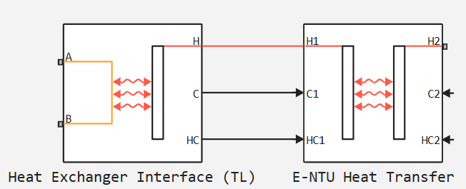
Block structure
A block is a composite component built from simpler blocks.: Heat Exchanger Interface (TL) and E-NTU Heat Transfer.
Ports
Conserving
#
A1
—
thermal liquid inlet or outlet
thermal liquid
Details
Inlet or outlet port for thermal liquid on the corresponding side of the heat exchanger.
| Program usage name |
|
#
B1
—
thermal liquid inlet or outlet
thermal liquid
Details
Inlet or outlet port for thermal liquid on the corresponding side of the heat exchanger.
| Program usage name |
|
#
H2
—
inlet temperature of the regulated heat transfer fluid
`heat
Details
Non-directional port related to the inlet temperature of the regulated heat transfer fluid.
| Program usage name |
|
Input
#
C2
—
flow heat capacity of the regulated coolant
scalar
Details
Input port that receives the value of the flow heat capacity of the regulated coolant.
| Data types |
|
| Complex numbers support |
No |
#
HC2
—
heat transfer coefficient of the regulated coolant
scalar
Details
Heat transfer coefficient between the regulated fluid and the separating wall.
| Data types |
|
| Complex numbers support |
No |
Parameters
Thermal Liquid
# Reynolds number vector for Darcy friction factor — the Reynolds number at each reference point of the Darcy coefficient of friction lookup table
Details
The Reynolds number at each reference point of the Darcy coefficient of friction lookup table. The block performs an inter- and extrapolation of the values of the table to determine the Darcy coefficient of friction for any Reynolds number. Interpolation is performed using a linear function, and extrapolation is performed to the nearest value.
The values of the Reynolds numbers must be greater than zero and monotonously increase from left to right. They can cover laminar, transient and turbulent modes. The dimension of this vector must match the dimension of the vector Darcy friction factor vector to calculate tabulated reference points.
Dependencies
To use this parameter, set for the parameter Pressure loss model meaning Tabulated data - Darcy friction factor vs. Reynolds number.
| Default value |
|
| Program usage name |
|
| Evaluatable |
Yes |
# Euler number vector — the Euler number at each reference point of the Reynolds number lookup table
Details
The Euler number at each reference point of the Reynolds number lookup table. The block performs an inter- and extrapolation of the values of the table to determine the Reynolds number for any Euler number. Interpolation is performed using a linear function, and extrapolation is performed to the nearest value.
The values of the Darcy coefficient of friction should not be negative and should be arranged from left to right in ascending order of the corresponding Reynolds numbers. The dimension of this vector must match the dimension of the vector Reynolds number vector for Euler number to calculate tabulated reference points.
Dependencies
To use this parameter, set for the parameter Pressure loss model meaning Tabulated data - Euler number vs. Reynolds number.
| Default value |
|
| Program usage name |
|
| Evaluatable |
Yes |
#
Heat transfer surface area —
the effective surface area used in heat transfer between the heat carrier and the wall
m^2 | um^2 | mm^2 | cm^2 | km^2 | in^2 | ft^2 | yd^2 | mi^2 | ha | ac
Details
The effective surface area used in heat transfer between the heat carrier and the wall. The effective surface area is the sum of the primary and secondary surface areas, the area on which the wall is exposed to the liquid, and the area of the ribs, if any. The surface area of the ribs is usually calculated by the efficiency coefficient of the ribs.
| Units |
|
| Default value |
|
| Program usage name |
|
| Evaluatable |
Yes |
#
Minimum free-flow area —
the cross-sectional area of the channel at its narrowest point
m^2 | um^2 | mm^2 | cm^2 | km^2 | in^2 | ft^2 | yd^2 | mi^2 | ha | ac
Details
The minimum cross-sectional area of the channel through which the coolant flows between the inlet and outlet. If it is a set of channels, tubes, slits, or grooves, then the value of the parameter is defined as the sum of the smallest areas at the point of the minimum flow area.
| Units |
|
| Default value |
|
| Program usage name |
|
| Evaluatable |
Yes |
#
Liquid-wall heat transfer coefficient —
coefficient of heat transfer during convection between a heat-conducting liquid and a wall
W/(m^2*K) | Btu_IT/(hr*ft^2*deltadegR)
Details
The heat transfer coefficient for convection between the gas and the wall. The resistance caused by deposits is taken into account separately in the parameter Fouling factor.
Dependencies
To use this parameter, set for the parameter Heat transfer coefficient model meaning Constant heat transfer coefficient.
| Units |
|
| Default value |
|
| Program usage name |
|
| Evaluatable |
Yes |
# Reynolds number vector for Euler number — the Reynolds number at each reference point of the Euler number lookup table
Details
The Reynolds number at each reference point of the Euler number lookup table. The block performs an inter- and extrapolation of the values of the table to determine the Euler number for any Reynolds number. Interpolation is performed using a linear function, and extrapolation is performed to the nearest value.
The values of the Reynolds numbers must be greater than zero and monotonously increase from left to right. They can cover laminar, transient and turbulent modes. The dimension of this vector must match the dimension of the vector Euler number vector to calculate tabulated reference points.
Dependencies
To use this parameter, set for the parameter Pressure loss model meaning Tabulated data - Euler number vs. Reynolds number.
| Default value |
|
| Program usage name |
|
| Evaluatable |
Yes |
#
Length of flow path from inlet to outlet —
distance traveled from port to port
m | um | mm | cm | km | in | ft | yd | mi | nmi
Details
The total distance that the stream must travel between the ports. In multi-pass shell-and-tube heat exchangers, the total distance is the sum of all passes through the casing. In tube bundles, corrugated plates, and other channels where the flow is divided into parallel branches, this is the distance traveled in one branch. The longer the flow path, the greater the main pressure loss due to viscous friction against the walls.
Dependencies
To use this parameter, set for the parameter Pressure loss model meaning Correlation for flow inside tubes or Tabulated data - Darcy friction factor vs. Reynolds number.
| Units |
|
| Default value |
|
| Program usage name |
|
| Evaluatable |
Yes |
# Laminar flow upper Reynolds number limit — the lower boundary of the transition zone between laminar and turbulent flow regimes
Details
The value of the Reynolds number corresponding to the lower boundary of the transition zone between laminar and turbulent flow regimes. Above this value, inertial forces begin to dominate, as a result of which the flow passes from laminar to turbulent mode. The default value corresponds to a round tube with a smooth inner surface.
| Default value |
|
| Program usage name |
|
| Evaluatable |
Yes |
#
Pressure loss model —
mathematical model for calculating pressure losses due to viscous friction
Pressure loss coefficient | Correlation for flow inside tubes | Tabulated data - Darcy friction factor vs. Reynolds number | Tabulated data - Euler number vs. Reynolds number
Details
This parameter allows you to select one of the models for calculating pressure losses due to viscous friction. The parameter determines which expressions will be used in calculating losses, as well as which block parameters must be set at the input. The details of the calculations, depending on the chosen parameterization, are given in the block Heat Exchanger Interface (TL).
| Values |
|
| Default value |
|
| Program usage name |
|
| Evaluatable |
No |
# Pressure loss coefficient — total coefficient that takes into account hydraulic losses between ports
Details
The total loss coefficient takes into account all hydraulic flow resistances in the channel, including wall friction losses (major losses) and local resistances due to bends, bends and other geometry changes (minor losses).
The loss coefficient is an empirical dimensionless quantity widely used to describe pressure losses caused by viscous friction. It can be calculated based on experimental data or, in some cases, obtained from technical documentation.
Dependencies
To use this parameter, set for the parameter Pressure loss model meaning Pressure loss coefficient.
| Default value |
|
| Program usage name |
|
| Evaluatable |
Yes |
# Nusselt number table, Nu(Re,Pr) — the Nusselt number at each reference point of the Reynolds—Prandtl number lookup table
Details
The Nusselt number at each reference point of the Reynolds—Prandtl number lookup table. The block performs an inter- and extrapolation of the values of the table to determine the Nusselt number for any pair of Reynolds—Prandtl numbers. Interpolation is performed using a linear function, and extrapolation is performed to the nearest value. By defining the Nusselt number, the table provides data for a calculation based on which the heat transfer coefficient between the liquid and the wall is determined.
The Nusselt number must be greater than zero. Each value should be placed from top to bottom in ascending order of Reynolds numbers and from left to right in ascending order of Prandtl numbers. The number of rows must be equal to the dimension of the vector. Reynolds number vector for Nusselt number, and the number of columns should be equal to the dimension of the vector Prandtl number vector for Nusselt number.
Dependencies
To use this parameter, set for the parameter Heat transfer coefficient model meaning Tabulated data - Nusselt number vs. Reynolds number and Prandtl number.
| Default value |
|
| Program usage name |
|
| Evaluatable |
Yes |
#
Fouling factor —
thermal resistance due to deposits
K*m^2/W | deltadegR*ft^2*hr/Btu_IT
Details
Thermal resistance due to deposits that form over time on the exposed wall surfaces. Deposits, because they create a new solid layer between the coolant and the wall through which heat must pass, add additional thermal resistance to the heat transfer path. Deposits grow slowly, and the resistance caused by them is assumed to be constant during the simulation.
| Units |
|
| Default value |
|
| Program usage name |
|
| Evaluatable |
Yes |
#
Internal surface absolute roughness —
the average height of the roughness on the wall surface, which leads to viscous friction losses
m | um | mm | cm | km | in | ft | yd | mi | nmi
Details
The average height of the roughness on the wall surface, which leads to viscous friction losses. The higher the average height, the rougher the wall and the greater the pressure loss due to viscous friction. The surface roughness value is used to obtain the Darcy coefficient of friction from the Haaland ratio.
Dependencies
To use this parameter, set for the parameter Pressure loss model meaning Correlation for flow inside tubes.
| Units |
|
| Default value |
|
| Program usage name |
|
| Evaluatable |
Yes |
# Darcy friction factor vector — the Darcy coefficient of friction at each reference point of the Reynolds number lookup table
Details
The Darcy coefficient of friction at each reference point of the Reynolds number lookup table. The block performs an inter- and extrapolation of the values of the table to determine the Darcy coefficient of friction for any Reynolds number. Interpolation is performed using a linear function, and extrapolation is performed to the nearest value.
The values of the Darcy coefficient of friction should not be negative and should be arranged from left to right in ascending order of the corresponding Reynolds numbers. The dimension of this vector must match the dimension of the vector Reynolds number vector for Darcy friction factor to calculate tabulated reference points.
Dependencies
To use this parameter, set for the parameter Pressure loss model meaning Tabulated data - Darcy friction factor vs. Reynolds number.
| Default value |
|
| Program usage name |
|
| Evaluatable |
Yes |
# Colburn factor vector — the Colburn factor at each reference point of the Reynolds number lookup table
Details
The Colburn factor at each reference point of the Reynolds number lookup table. The block performs an inter- and extrapolation of the values of the table to determine the Reynolds number for any Colburn factor. Interpolation is performed using a linear function, and extrapolation is performed to the nearest value.
The values of the Colburn factor should not be negative and should be arranged from left to right in ascending order of the corresponding Reynolds numbers. The dimension of this vector must match the dimension of the vector Reynolds number vector for Colburn factor to calculate tabulated reference points.
Dependencies
To use this parameter, set for the parameter Heat transfer coefficient model meaning Tabulated data - Colburn factor vs. Reynolds number.
| Default value |
|
| Program usage name |
|
| Evaluatable |
Yes |
#
Minimum fluid-wall heat transfer coefficient —
lower bound for the gas heat transfer coefficient
W/(m^2*K) | Btu_IT/(hr*ft^2*deltadegR)
Details
The lower bound for the heat transfer coefficient between the gas and the wall. If the calculation gives a lower heat transfer coefficient, then the value Minimum fluid-wall heat transfer coefficient replaces the calculated value.
| Units |
|
| Default value |
|
| Program usage name |
|
| Evaluatable |
Yes |
# Reynolds number vector for Colburn factor — the Reynolds number at each reference point of the Colburn factor lookup table
Details
The Reynolds number at each reference point of the Colburn factor lookup table. The block performs an inter- and extrapolation of the values of the table to determine the Colburn factor for any Reynolds number. Interpolation is performed using a linear function, and extrapolation is performed to the nearest value.
The values of the Reynolds numbers must be greater than zero and monotonously increase from left to right. They can cover laminar, transient and turbulent modes. The dimension of this vector must match the dimension of the vector Colburn factor vector to calculate tabulated reference points.
Dependencies
To use this parameter, set for the parameter Heat transfer coefficient model meaning Tabulated data - Colburn factor vs. Reynolds number.
| Default value |
|
| Program usage name |
|
| Evaluatable |
Yes |
#
Length of flow path for heat transfer —
the characteristic length traveled during heat transfer between the gas and the wall
m | um | mm | cm | km | in | ft | yd | mi | nmi
Details
The characteristic length traveled during heat transfer between the gas and the wall. This length is taken into account when calculating the hydraulic diameter, on which the heat transfer coefficient and the Reynolds number in the tabular heat transfer parameterizations depend.
Dependencies
To use this parameter, set for the parameter Heat transfer coefficient model meaning Tabulated data - Colburn factor vs. Reynolds number or Tabulated data - Nusselt number vs. Reynolds number and Prandtl number.
| Units |
|
| Default value |
|
| Program usage name |
|
| Evaluatable |
Yes |
#
Thermal Liquid volume —
the total volume of the coolant in the channel of the heat-conducting liquid
m^3 | um^3 | mm^3 | cm^3 | km^3 | ml | l | gal | igal | in^3 | ft^3 | yd^3 | mi^3
Details
The total volume of the coolant contained in the channel of the heat-conducting liquid.
| Units |
|
| Default value |
|
| Program usage name |
|
| Evaluatable |
Yes |
#
Aggregate equivalent length of local resistances —
total local pressure losses, expressed in length
m | um | mm | cm | km | in | ft | yd | mi | nmi
Details
Total local pressure losses, expressed in length. The length of the direct channel leads to equivalent losses equal to the sum of the existing local resistances of the taps, tees and joints. The longer the equivalent length, the higher the pressure loss due to local resistances.
Dependencies
To use this parameter, set for the parameter Pressure loss model meaning Correlation for flow inside tubes.
| Units |
|
| Default value |
|
| Program usage name |
|
| Evaluatable |
Yes |
#
Heat transfer coefficient model —
mathematical model for heat exchange between a heat carrier and a wall
Constant heat transfer coefficient | Correlation for flow inside tubes | Tabulated data - Colburn factor vs. Reynolds number | Tabulated data - Nusselt number vs. Reynolds number and Prandtl number
Details
A mathematical model for heat transfer between a heat carrier and a wall. The choice of the model determines which expressions to use and which parameters to specify for heat transfer calculations.
For more information, see the section E-NTU Heat Transfer.
| Values |
|
| Default value |
|
| Program usage name |
|
| Evaluatable |
No |
# Nusselt number for laminar flow heat transfer — the constant value of the Nusselt number for laminar flow
Details
The constant value of the Nusselt number for laminar flows. The Nusselt number is necessary to calculate the heat transfer coefficient between the coolant and the wall. The default value corresponds to a cylindrical tube.
Dependencies
To use this parameter, set for the parameter Heat transfer coefficient model meaning Correlation for flow inside tubes.
| Default value |
|
| Program usage name |
|
| Evaluatable |
Yes |
# Prandtl number vector for Nusselt number — the Prandtl number at each reference point of the Nusselt number lookup table
Details
The Prandtl number at each reference point of the Nusselt number lookup table. The table is two-parameter, where the Reynolds and Prandtl numbers are used as independent coordinates. The block performs an inter- and extrapolation of the values of the table to determine the Nusselt number for any Prandtl number. Interpolation is performed using a linear function, and extrapolation is performed to the nearest value.
The values of the Prandtl numbers must be greater than zero and monotonously increase from left to right. They can cover laminar, transient and turbulent modes. The dimension of this vector should correspond to the number of columns in the table. Nusselt number table, Nu(Re,Pr). If the table has lines and columns, then the Prandtl number vector must be of length elements.
Dependencies
To use this parameter, set for the parameter Heat transfer coefficient model meaning Tabulated data - Nusselt number vs. Reynolds number and Prandtl number.
| Default value |
|
| Program usage name |
|
| Evaluatable |
Yes |
# Reynolds number vector for Nusselt number — the Reynolds number at each reference point of the Nusselt number lookup table
Details
The Reynolds number at each reference point of the Nusselt number lookup table. The table is two-parameter, where the Reynolds and Prandtl numbers are used as independent coordinates. The block performs an inter- and extrapolation of the values of the table to determine the Nusselt number for any Reynolds number. Interpolation is performed using a linear function, and extrapolation is performed to the nearest value.
The values of the Reynolds numbers must be greater than zero and monotonously increase from left to right. They can cover laminar, transient and turbulent modes. The dimension of this vector should correspond to the number of rows in the table. Nusselt number table, Nu(Re,Pr). If the table has lines and columns, then the Reynolds number vector must be of length elements.
Dependencies
To use this parameter, set for the parameter Heat transfer coefficient model meaning Tabulated data - Nusselt number vs. Reynolds number and Prandtl number.
| Default value |
|
| Program usage name |
|
| Evaluatable |
Yes |
# Turbulent flow lower Reynolds number limit — the upper boundary of the transition zone between laminar and turbulent flow regimes
Details
The value of the Reynolds number corresponding to the upper boundary of the transition zone between laminar and turbulent flow regimes. Below this value, viscous forces begin to dominate, as a result of which the flow passes from a turbulent to a laminar regime. The default value corresponds to a round tube with a smooth inner surface.
| Default value |
|
| Program usage name |
|
| Evaluatable |
Yes |
#
Hydraulic diameter for pressure loss —
the hydraulic diameter of the channel at its narrowest point
m | um | mm | cm | km | in | ft | yd | mi | nmi
Details
The effective internal diameter of the channel in the section with the smallest area. For non—circular channels, the hydraulic diameter is the equivalent diameter of a circle with an area equal to the area of the existing channel. Its value is equal to the ratio of the minimum cross-sectional area of the channel to a quarter of its total perimeter.
If a channel is defined by a set of channels, pipes, slots, or grooves, then the total perimeter is equal to the sum of the perimeters of all the elements. If the channel is a round pipe, then its hydraulic diameter is equal to the actual one.
| Units |
|
| Default value |
|
| Program usage name |
|
| Evaluatable |
Yes |
# Laminar friction constant for Darcy friction factor — correction for pressure loss for flow cross-section under laminar flow conditions
Details
Correction for pressure loss for laminar flow. This parameter is called the shape coefficient and can be used to obtain the Darcy coefficient of friction when calculating pressure losses in the laminar regime. The default value corresponds to cylindrical pipes.
Some additional shape coefficients for non-circular sections can be determined from analytical solutions of the Navier-Stokes equations. An air duct with a square cross-section has a shape coefficient 56, an air duct with a rectangular cross-section with an aspect ratio of 2:1 has a shape coefficient 62, and the coaxial pipe has a shape coefficient 96. The thin channel between the parallel plates also has a shape coefficient 96.
Dependencies
To use this parameter, set for the parameter Pressure loss model meaning Correlation for flow inside tubes.
| Default value |
|
| Program usage name |
|
| Evaluatable |
Yes |
Controlled Fluid
#
Minimum fluid-wall heat transfer coefficient —
the lower limit for the heat transfer coefficient of the regulated coolant
W/(m^2*K) | Btu_IT/(hr*ft^2*deltadegR)
Details
The lower limit for the heat transfer coefficient between the coolant and the wall. If the calculation gives a lower heat transfer coefficient, then the value Minimum fluid-wall heat transfer coefficient replaces the calculated value.
| Units |
|
| Default value |
|
| Program usage name |
|
| Evaluatable |
Yes |
#
Heat transfer surface area —
the effective surface area used in heat transfer between the heat carrier and the wall
m^2 | um^2 | mm^2 | cm^2 | km^2 | in^2 | ft^2 | yd^2 | mi^2 | ha | ac
Details
The effective surface area used in heat transfer between the heat carrier and the wall. The effective surface area is the sum of the primary and secondary surface areas, the area on which the wall is exposed to the liquid, and the area of the ribs, if any. The surface area of the ribs is usually calculated by the efficiency coefficient of the ribs.
| Units |
|
| Default value |
|
| Program usage name |
|
| Evaluatable |
Yes |
#
Fouling factor —
thermal resistance due to deposits
K*m^2/W | deltadegR*ft^2*hr/Btu_IT
Details
Thermal resistance due to deposits that form over time on the exposed wall surfaces. Deposits, because they create a new solid layer between the coolant and the wall through which heat must pass, add additional thermal resistance to the heat transfer path. Deposits grow slowly, and the resistance caused by them is assumed to be constant during the simulation.
| Units |
|
| Default value |
|
| Program usage name |
|
| Evaluatable |
Yes |
Effects and Initial Conditions
#
Thermal Liquid initial temperature —
the temperature of the heat-conducting liquid in the channel at the beginning of the simulation
K | degC | degF | degR | deltaK | deltadegC | deltadegF | deltadegR
Details
The temperature of the heat-conducting liquid in the channel at the beginning of the simulation.
| Units |
|
| Default value |
|
| Program usage name |
|
| Evaluatable |
Yes |
# Thermal Liquid 1 dynamic compressibility — compressibility of a heat-conducting liquid in a heat exchanger
Details
An option for simulating pressure changes inside the heat exchanger. If this option is unchecked, then the pressure derivatives are not taken into account in the equations of conservation of energy and mass. The pressure inside the heat exchanger is defined as the average of the two port pressures.
| Default value |
|
| Program usage name |
|
| Evaluatable |
No |
#
Thermal Liquid initial pressure —
the pressure of the heat-conducting liquid in the channel at the beginning of the simulation
Pa | uPa | hPa | kPa | MPa | GPa | kgf/m^2 | kgf/cm^2 | kgf/mm^2 | mbar | bar | kbar | atm | ksi | psi | mmHg | inHg
Details
The pressure of the heat-conducting liquid in the channel at the beginning of the simulation.
| Units |
|
| Default value |
|
| Program usage name |
|
| Evaluatable |
Yes |
Common
# Effectiveness table, E(NTU,CR) — the efficiency of the heat exchanger at each reference point of the search table by the number of transfer units and the coefficient of heat capacity
Details
The heat exchanger efficiency values at the reference points of a two-dimensional table defined by coordinates: the number of heat transfer units and the heat capacity coefficient. The block performs an inter- and extrapolation of the values of the table to determine the effectiveness of arbitrary combinations of the specified parameters. Interpolation is performed using a linear function, and extrapolation is performed to the nearest value.
The efficiency values should be non-negative. They should be arranged in rows in ascending order of the number of transfer units (from top to bottom), and in columns in ascending order of the heat capacity coefficient (from left to right). The number of rows must match the dimension of the vector. Number of heat transfer units vector, NTU, and the number of columns is the dimension of the vector Thermal capacity ratio vector, CR.
Dependencies
To use this parameter, set for the parameter Flow arrangement meaning Generic - effectiveness table.
| Default value |
|
| Program usage name |
|
| Evaluatable |
Yes |
#
Flow arrangement —
flow diagram of heat carriers in the heat exchanger
Parallel or counter flow | Shell and tube | Cross flow | Generic - effectiveness table
Details
The parameter that defines the relative arrangement of the flows in the heat exchanger: direct flow, countercurrent, across each other (transverse), as well as the "pipe in the casing" design, in which one flow passes inside the pipes and the other outside, in the casing.
Alternative flow patterns of heat carriers can be specified in an arbitrary efficiency table, which does not require detailed specifications of the heat exchanger.
| Values |
|
| Default value |
|
| Program usage name |
|
| Evaluatable |
No |
#
Cross flow type —
the type of mixing in each channel
Both fluids mixed | Both fluids unmixed | Thermal Liquid mixed & Controlled Fluid unmixed | Thermal Liquid unmixed & Controlled Fluid mixed
Details
The type of coolant mixing in each channel. Mixing in this context is the transverse movement of the coolant as it moves along the channel to the outlet. The streams remain separate from each other. Immiscible flows are often found in channels with plates, baffles, or ribs. This characteristic affects the efficiency of the heat exchanger: unmixed flows are the most efficient, while mixed flows are less efficient.
_ Dependencies_
To use this parameter, set for the parameter Flow arrangement meaning Shell and tube.
| Values |
|
| Default value |
|
| Program usage name |
|
| Evaluatable |
No |
# Number of shell passes — the number of flow passages in the casing before exiting
Details
The number of strokes of the flow through the casing in the shell-and-tube heat exchanger.
Dependencies
To use this parameter, set for the parameter Flow arrangement meaning Shell and tube.
| Default value |
|
| Program usage name |
|
| Evaluatable |
Yes |
#
Wall thermal resistance —
wall resistance to heat flow due to thermal conductivity
K/W
Details
The resistance of the wall to heat flow due to thermal conductivity and the inverse of thermal conductivity, or the product of thermal conductivity by the ratio of surface area to length. The wall resistance is combined with convective resistance and sediment resistance to determine the overall heat transfer coefficient between the flows.
| Units |
|
| Default value |
|
| Program usage name |
|
| Evaluatable |
Yes |
# Number of heat transfer units vector, NTU — the number of heat transfer units at each reference point of the heat exchanger efficiency lookup table
Details
The number of heat transfer units at each reference point of the heat exchanger efficiency lookup table. The table is two-dimensional, and the number of heat transfer units and the heat capacity coefficient act as independent coordinates. The block performs an inter- and extrapolation of reference points to determine efficiency at any value of the number of transfer units. Interpolation is performed using a linear function, and extrapolation is performed to the nearest value.
The specified numbers must be greater than zero and monotonously increase from left to right. The dimension of this vector should correspond to the number of rows in the table. Effectiveness table, E(NTU,CR). If the table has lines and columns, then the vector for the number of transfer units must be long elements.
_ Dependencies_
To use this parameter, set for the parameter Flow arrangement meaning Generic - effectiveness table.
| Default value |
|
| Program usage name |
|
| Evaluatable |
Yes |
# Thermal capacity ratio vector, CR — heat capacity coefficient at each reference point of the heat exchanger efficiency table
Details
The values of the heat capacity coefficient corresponding to the reference points in the heat exchanger efficiency table. The table is two-dimensional, and the number of heat transfer units and the heat capacity coefficient act as independent coordinates. The unit performs an inter- and extrapolation of reference points to determine efficiency at any value of the heat capacity coefficient. Interpolation is performed using a linear function, and extrapolation is performed to the nearest value.
The coefficients must be positive and strictly increase from left to right. The dimension of the vector must correspond to the number of columns in the table. Effectiveness table, E(NTU,CR). If the table has lines and If there are no columns, then the vector of heat capacity coefficients should be long elements.
The heat capacity coefficient is the ratio of the minimum and maximum values of the flow heat capacity.
_ Dependencies_
To use this parameter, set for the parameter Flow arrangement meaning Generic - effectiveness table.
| Default value |
|
| Program usage name |
|
| Evaluatable |
Yes |