Specific Dissipation Heat Exchanger (TL)
A heat exchanger parameterized based on data on the relative magnitude of heat transfer for systems with a flow of heat-conducting liquid and a controlled flow.
blockType: EngeeFluids.HeatExchangers.SpecificDissipation.ThermalLiquid
|
Path in the library: |

Description
Block Specific Dissipation Heat Exchanger (TL) simulates the cooling and heating of heat carriers through thermal conduction through a thin wall. Heat exchange between heat carriers is based on contact heat exchange with a heat-conducting liquid.

The heat transfer model
Heat transfer according to a simple model is based on the relative magnitude of heat transfer:
where
-
— the relative value of heat transfer, depending on the mass flow rate of the heat-conducting liquid and the controlled flow;
-
— temperature of the heat-conducting liquid at the inlet;
-
— the temperature of the regulated inlet flow.
The simple model is based on linear interpolation of tabular data provided by the user and does not take into account the individual characteristics of the heat exchanger.
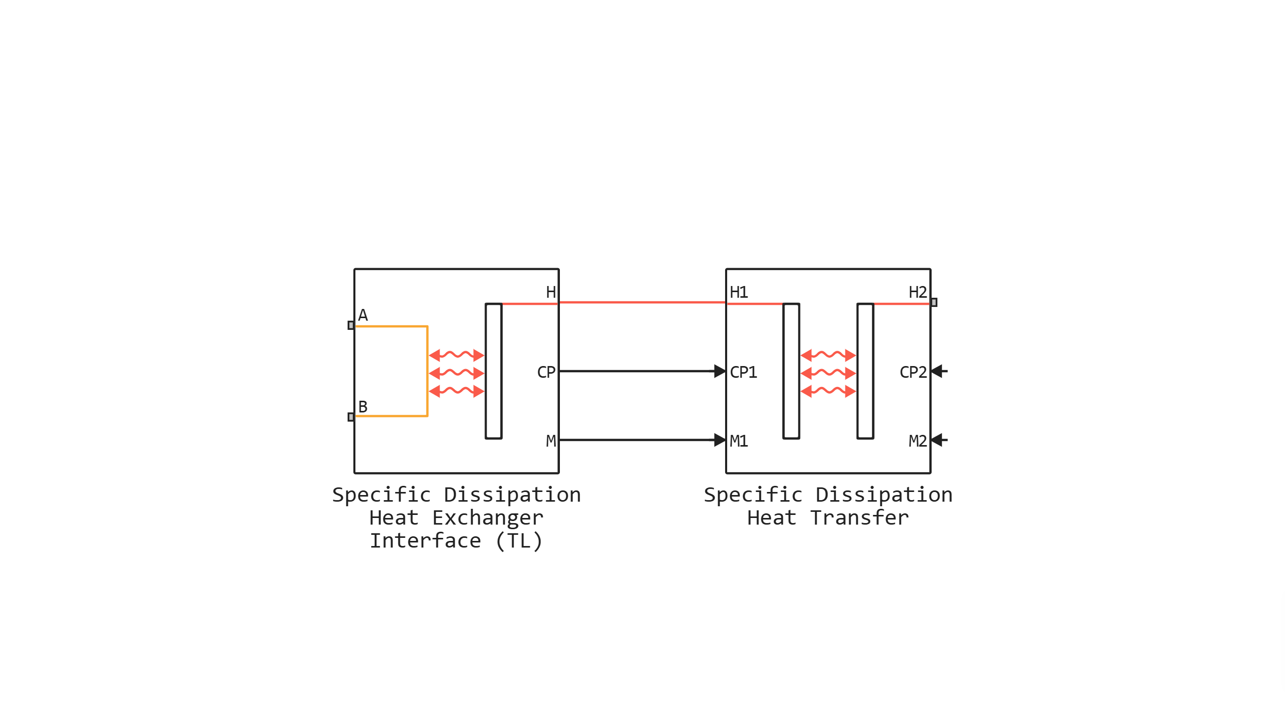
Block structure
Block Specific Dissipation Heat Exchanger (TL) It consists of blocks Specific Dissipation Heat Exchanger Interface (TL) and Specific Dissipation Heat Transfer:
Ports
Conserving
#
A1
—
inlet or outlet of the thermal liquid
thermal liquid
Details
The inlet or outlet port for the thermal liquid on the corresponding side of the heat exchanger.
| Program usage name |
|
#
B1
—
inlet or outlet of the thermal liquid
thermal liquid
Details
The inlet or outlet port for the thermal liquid on the corresponding side of the heat exchanger.
| Program usage name |
|
#
H2
—
the temperature of the regulated coolant at the inlet
warmth
Details
The temperature of the regulated coolant at the inlet.
| Program usage name |
|
Input
#
CP2
—
isobaric specific heat capacity of the regulated coolant
scalar
Details
The instantaneous value of the isobaric specific heat capacity of the regulated coolant.
| Data types |
|
| Complex numbers support |
I don’t |
#
M2
—
mass flow rate of the regulated coolant
scalar
Details
The instantaneous value of the mass flow of the regulated coolant.
| Data types |
|
| Complex numbers support |
I don’t |
Parameters
Heat Transfer
#
Controlled fluid mass flow rate vector, mdot2 —
the mass flow rate of the controlled coolant at each break point in the interpolation table for the relative heat transfer value table
kg/s | kg/hr | kg/min | g/hr | g/min | g/s | t/hr | lbm/hr | lbm/min | lbm/s
Details
The mass flow rate of the controlled coolant at each break point in the interpolation table for the relative heat transfer value table. The unit interpolates and extrapolates the values of the break points to obtain the relative heat transfer value of the heat exchanger at any mass flow rate.
The mass flow values can be positive, zero, or negative, but they must monotonously increase from left to right. Their number should be equal to the number of columns in the parameter. Specific dissipation table, SD(mdot1, mdot2). If the table contains lines and For example, the vector of mass flow values should contain elements.
| Units |
|
| Default value |
|
| Program usage name |
|
| Evaluatable |
Yes |
#
Thermal Liquid mass flow rate vector, mdot1 —
the mass flow rate of the heat-conducting liquid at each break point in the interpolation table for the relative heat transfer value table
kg/s | kg/hr | kg/min | g/hr | g/min | g/s | t/hr | lbm/hr | lbm/min | lbm/s
Details
The mass flow rate of the heat-conducting liquid at each break point in the interpolation table for the relative heat transfer value table. The unit interpolates and extrapolates the values of the break points to obtain the relative heat transfer value of the heat exchanger at any mass flow rate.
The mass flow values can be positive, zero, or negative, but they should increase monotonously from left to right. Their number should be equal to the number of columns in the parameter. Specific dissipation table, SD(mdot1, mdot2). If the table contains lines and For example, the vector of mass flow values should contain elements.
| Units |
|
| Default value |
|
| Program usage name |
|
| Evaluatable |
Yes |
#
Check if violating maximum specific dissipation —
the status of the warning about the relative value of heat transfer exceeding the minimum flow heat capacity
None | Error
Details
A warning about the relative heat transfer value exceeding the minimum flow heat capacity. The flow heat capacity is the product of mass flow and specific heat, and its minimum value is the smallest of the two flows. This minimum determines the relative amount of heat transfer for a heat exchanger with maximum efficiency and cannot be exceeded. For more information, see the description of the block. Specific Dissipation Heat Transfer.
| Values |
|
| Default value |
|
| Program usage name |
|
| Evaluatable |
No |
#
Specific dissipation table, SD(mdot1, mdot2) —
the relative value of heat transfer at each break point in the interpolation table of mass flow rates of a heat-conducting liquid and a regulated coolant
W/K | kW/K
Details
The relative value of heat transfer at each break point is shown in the interpolation table of mass flow rates of a heat-conducting liquid and a regulated coolant. The unit interpolates and extrapolates the values of the break points to obtain efficiency for any pair of mass flow rates of a heat-conducting liquid and a regulated coolant.
The values of the relative heat transfer value should not be negative. They must be aligned from top to bottom in the order of increasing mass flow in the channel for the heat-conducting liquid and from left to right in the order of increasing mass flow in the channel for the controlled coolant. The number of rows must be equal to the parameter size. Thermal Liquid mass flow rate vector, mdot1, and the number of columns corresponds to the size of the parameter Controlled fluid mass flow rate vector, mdot2.
If the heat transfer coefficients are specified in the technical data sheet of your heat exchanger, multiply the indicated heat transfer coefficients by the surface area to calculate the relative amount of heat transfer.
| Units |
|
| Default value |
|
| Program usage name |
|
| Evaluatable |
Yes |
Pressure Loss
#
Mass flow rate vector —
mass flow rate at each break point in the interpolation table for pressure drop
kg/s | kg/hr | kg/min | g/hr | g/min | g/s | t/hr | lbm/hr | lbm/min | lbm/s
Details
The mass flow rate at each break point in the interpolation table of differential pressure values. The unit interpolates and extrapolates the values of the break points to obtain a pressure drop value for any mass flow rate.
The mass flow values can be positive, zero, or negative and can cover laminar, transient, and turbulent zones. However, they should monotonously increase from left to right. Their number must match the size of the parameter. Pressure drop vector, with which they are combined to form tabular breakpoints.
| Units |
|
| Default value |
|
| Program usage name |
|
| Evaluatable |
Yes |
#
Cross-sectional area at ports A1 and B1 —
the cross-sectional area of the flow at the inlet and outlet of the passage channel
m^2 | um^2 | mm^2 | cm^2 | km^2 | in^2 | ft^2 | yd^2 | mi^2 | ha | ac
Details
The cross-sectional area of the flow at the inlet and outlet of the channel for supplying heat-conducting liquid. The ports have the same size.
| Units |
|
| Default value |
|
| Program usage name |
|
| Evaluatable |
Yes |
#
Pressure drop vector —
pressure drop at each break point in the mass flow interpolation table
Pa | uPa | hPa | kPa | MPa | GPa | kgf/m^2 | kgf/cm^2 | kgf/mm^2 | mbar | bar | kbar | atm | ksi | psi | mmHg | inHg
Details
The pressure drop at each break point in the mass flow interpolation table. The unit interpolates and extrapolates the break points to obtain a pressure drop value for any mass flow rate.
The pressure drop values can be positive, zero, or negative and can cover laminar, transient, and turbulent zones. However, they should monotonously increase from left to right. Their number must match the size of the parameter. Mass flow rate vector, with which they are combined to form tabular breakpoints.
| Units |
|
| Default value |
|
| Program usage name |
|
| Evaluatable |
Yes |
#
Reference inflow temperature —
the absolute temperature at the inlet, accepted in the tabular data
K | degC | degF | degR | deltaK | deltadegC | deltadegF | deltadegR
Details
The absolute inlet temperature is determined by collecting tabular pressure drop data. The reference temperature and inlet pressure determine the density of the fluid assumed in the tabular data. During the simulation, the ratio of the reference fluid density to the actual one is multiplied by the differential pressure value shown in the table to obtain the actual pressure drop.
| Units |
|
| Default value |
|
| Program usage name |
|
| Evaluatable |
Yes |
#
Thermal Liquid volume —
the volume of liquid in the channel for supplying heat-conducting liquid
m^3 | um^3 | mm^3 | cm^3 | km^3 | ml | l | gal | igal | in^3 | ft^3 | yd^3 | mi^3
Details
The volume of liquid in the channel for supplying heat-conducting liquid.
| Units |
|
| Default value |
|
| Program usage name |
|
| Evaluatable |
Yes |
#
Mass flow rate threshold for flow reversal —
the upper bound of the numerically smoothed region for mass flow
kg/s | kg/hr | kg/min | g/hr | g/min | g/s | t/hr | lbm/hr | lbm/min | lbm/s
Details
The mass flow rate below which its value is numerically smoothed to avoid discontinuities that lead to simulation errors at zero flow. Detailed information about the calculations for the heat-conducting fluid side of the heat exchanger can be found in the description of the unit. Specific Dissipation Heat Exchanger Interface (TL).
| Units |
|
| Default value |
|
| Program usage name |
|
| Evaluatable |
Yes |
#
Reference inflow pressure —
the absolute inlet pressure assumed in the tabular data
Pa | uPa | hPa | kPa | MPa | GPa | kgf/m^2 | kgf/cm^2 | kgf/mm^2 | mbar | bar | kbar | atm | ksi | psi | mmHg | inHg
Details
The absolute inlet pressure is determined by collecting tabular pressure drop data. The reference temperature and inlet pressure determine the density of the fluid assumed in the tabular data. During the simulation, the ratio of the reference fluid density to the actual one is multiplied by the differential pressure value shown in the table to obtain the actual pressure drop.
| Units |
|
| Default value |
|
| Program usage name |
|
| Evaluatable |
Yes |
Effects and Initial Conditions
#
Thermal Liquid initial temperature —
the temperature in the channel for the supply of heat-conducting liquid at the beginning of the simulation
K | degC | degF | degR | deltaK | deltadegC | deltadegF | deltadegR
Details
The temperature in the channel for the supply of heat-conducting liquid at the beginning of the simulation.
| Units |
|
| Default value |
|
| Program usage name |
|
| Evaluatable |
Yes |
# Thermal Liquid dynamic compressibility — the ability to simulate pressure dynamics in a thermally conductive liquid
Details
The ability to simulate pressure dynamics in a thermally conductive liquid. If you uncheck this box, the block will remove the pressure derivatives from the equations of conservation of energy and mass of the components. The pressure inside the heat exchanger will be reduced to a weighted average of the two inlet pressures.
| Default value |
|
| Program usage name |
|
| Evaluatable |
No |
#
Thermal Liquid initial pressure —
pressure in the channel for the supply of heat-conducting liquid at the beginning of the simulation
Pa | uPa | hPa | kPa | MPa | GPa | kgf/m^2 | kgf/cm^2 | kgf/mm^2 | mbar | bar | kbar | atm | ksi | psi | mmHg | inHg
Details
The pressure in the channel for the supply of heat-conducting liquid at the beginning of the simulation.
| Units |
|
| Default value |
|
| Program usage name |
|
| Evaluatable |
Yes |