Cylinder Cushion (IL)
The damper of the hydraulic cylinder in the isothermal fluid network.
blockType: EngeeFluids.IsothermalLiquid.Actuators.Auxiliary.CylinderCushion
|
Path in the library: |

Description
Block Cylinder Cushion (IL) It is a damper of a hydraulic cylinder with throttle braking in an isothermal fluid network. The damper slows down the cylinder rod as it nears the end of the stroke, limiting the flow of liquid exiting the piston cavity. The figure below shows a typical damper design [1].

As the piston moves towards the lid, which is located on the left in the figure, the shock-absorbing sleeve, or plunger, enters the counter hole in the lid (the damper cavity) and creates additional resistance to the liquid leaving the working cavity of the cylinder. The piston deceleration begins when the plunger enters the damper cavity in the lid and blocks the main liquid outlet. In this state, the liquid passes through the throttle valve and the minimum clearance. The valve restricts the flow of liquid coming out of the working cavity and slows down the piston.
The damper of the hydraulic cylinder consists of two holes – variable and constant cross-sections and a check valve. The hole of variable cross-section is a variable gap between the plunger and the notch in the end cap. The hole with a constant cross-section is a choke in the channel connecting the damper cavity to the piston cavity. The non-return valve ensures flow between the damper cavity and the piston cavity only during piston extension.
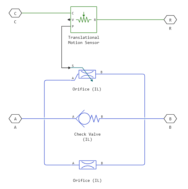
Block Cylinder Cushion (IL) — this is a composite component consisting of the following blocks:
-
Block Orifice (IL) simulates a throttle valve.
-
Block Check Valve (IL) simulates a check valve.
-
Block Orifice (IL) simulates the variable gap between the plunger and the end cap.
-
Block Absolute Translational Motion Sensor converts the distance between the plunger and the cavity in the end cap into a physical signal. This signal controls the degree of opening of the variable gap.
Block Cylinder Cushion (IL) It can be used to model hydraulic drives. A single-acting or double-acting hydraulic actuator may include dampers to slow down the movement of the piston near the stroke ends. The damper prevents hard impacts when the piston is stopped by the end caps.
Ports A and B are non—directional isothermal fluid ports connected to the fluid supply and piston cavity, respectively. The R port is a mechanical non—directional port connected to the piston plunger. Port C is a mechanical non—directional port connected to the clamping structure of the cylinder. The unit amortizes the flow from port B to port A. The check valve in the unit is oriented from port A to port B.
Variable hole area
In a block with a variable opening, it is assumed that when the plunger is far from the lid, the cross-section of the main fluid line is open and its area is equal to , where — diameter of the round plunger. When the plunger moves towards the lid, the liquid passes through the radial gap from the cylinder cavity into the counter hole on the lid. It is assumed that the area of the hole changes linearly with the movement of the piston between the maximum area and the leakage area. The area of the hole for this position of the piston is
where
-
— the area of the hole for the given position of the piston;
-
— leakage area between plunger and damper sleeve, parameter value Leakage area between plunger and cushion sleeve;
-
— the maximum hole size, which is equal to the value of the parameter Cushion plunger cross-sectional area;
-
— the position of the piston. Initial displacement of the piston — the value of the Actuator piston initial displacement parameter;
-
— has a value of
1when the parameter Actuator mechanical orientation is set toPressure at A causes positive displacement of R relative to C, and-1when the parameter Actuator mechanical orientation is set toPressure at A causes negative displacement of R relative to C; -
— the length of the shock-absorbing plunger, the value of the parameter Cushion plunger length;
-
— the diameter of the shock-absorbing plunger, the value of the parameter Cushion plunger diameter.
Numerical smoothing of area and pressure values
You can maintain numerical stability in the simulation by adjusting the Smoothing factor parameter. If the Smoothing factor parameter is not equal to zero, the values of the hole area and the control pressure of the check valve are smoothed. Provides a smooth change in the area of the hole between the parameters Leakage area between plunger and cushion sleeve and Cushion plunger cross-sectional area. The control pressure of the valve changes smoothly in the range between the parameters Check valve cracking pressure differential and Check valve maximum pressure differential.
Ports
Non-directional
A — pass inlet:q[<br>] isothermal liquid
The isothermal fluid port corresponding to the entrance to the damper cavity.
B — outlet
isothermal liquid
The port of the isothermal fluid corresponding to the outlet into the piston cavity.
R — stock
translational mechanics
A mechanical transfer port corresponding to the piston of the hydraulic cylinder.
C — housing
translational mechanics
A mechanical transfer port corresponding to the supporting structure of the hydraulic cylinder.
Parameters
Cushion Plunger
Cushion plunger cross-sectional area — cross−sectional area of the shock-absorbing plunger
1e-4 m2 (default) | positive scalar
The cross-sectional area of the shock-absorbing plunger. The area is equal to , where — diameter of the round plunger.
Cushion plunger length — the length of the shock−absorbing plunger
1e-3 m (default) | positive scalar
The length of the shock-absorbing plunger.
Initial actuator piston displacement — initial displacement of the piston
0 m (default) | scalar
Displacement of the piston in the cylinder at the beginning of the simulation. This offset determines the initial area of the variable hole, which models the variable gap between the plunger and the end cap.
Dependencies
If the value of the Actuator mechanical orientation parameter is set to Pressure at A causes positive displacement of R relative to C, then the value of the initial displacement of the piston must be greater than or equal to zero.
If the value of the Actuator mechanical orientation parameter is set to Pressure at A causes negative displacement of R relative to C, then the value of the initial displacement of the piston must be less than or equal to zero.
Actuator mechanical orientation — piston displacement direction
Pressure at A causes positive displacement of R relative to C (default) | Pressure at A causes negative displacement of R relative to C
The direction of movement of the piston of the connected drive unit. If this parameter is set to Pressure at A causes positive displacement of R relative to C, then the piston is extended at a positive value of R — C. If this parameter is set to Pressure at A causes negative displacement of R relative to C, the piston retracts at a positive value of R — C.
Valves
Cushion orifice area — opening area of the throttle valve
1e−6 m2 (default) | positive scalar
The constant area of the throttle valve opening through which liquid flows from the piston cavity when the plunger is inside the damper cavity.
Leakage area between plunger and cushion sleeve — total leakage area when the plunger is inside the hole in the pass cover:q[<br>] 1e−7 m2 (default) | positive scalar
The total area of possible leaks when the plunger is in the damper cavity. When the piston displacement is less than or equal to the value of the Cushion plunger length parameter, the area of the variable hole simulating the gap between the plunger and the lid is equal to the value of this parameter.
Check valve cracking pressure differential — pressure drop at which the check valve begins to open
0.01 MPa (default) | positive scalar
The minimum pressure drop through the check valve at which the valve begins to open. The check valve allows liquid to flow freely from the damper cavity into the piston cavity, but does not allow it to flow in the opposite direction.
Check valve maximum pressure differential — pressure drop required to fully open the check valve
0.1 MPa (default) | positive scalar
The pressure drop through the check valve required to fully open the valve. The value of this parameter must be greater than the value of the Check valve cracking pressure differential parameter. The check valve allows liquid to flow freely from the damper cavity into the piston cavity, but does not allow it to flow in the opposite direction.
Check valve maximum area — the area of the fully open check valve
1e−4 m2 (default) | positive scalar
The cross-sectional area of the non-return valve opening in the fully open position.
Check valve leakage area — total leakage area with the non-return valve fully closed
1e−10 m2 (default) | positive scalar
The total area of possible leaks when the check valve is fully closed.
Smoothing factor — numerical smoothing factor
0.01 (default) | positive scalar
The continuous smoothing coefficient, which ensures smooth opening by correcting for the valve characteristics in the almost open and almost closed positions. Set a non-zero value less than one to increase the stability of the simulation in these modes.