Double-Acting Actuator (TL-G)
Linear actuator with opposite chambers for heat-conducting liquid and gas.
blockType: EngeeFluids.ThermalLiquid.Actuators.TranslationalDoubleActingWithGasChamber
|
Path in the library: |

Description
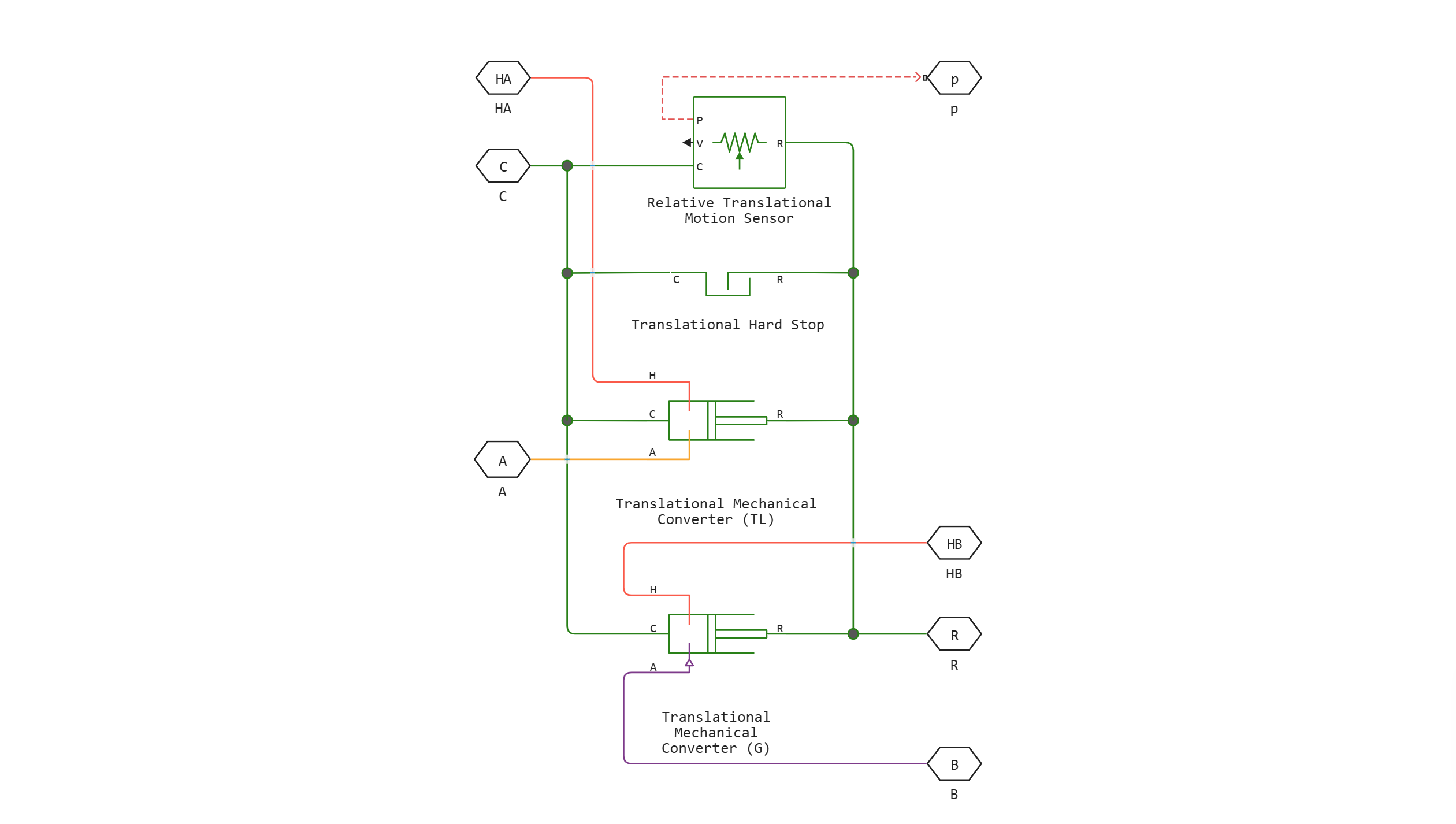
Block Double-Acting Actuator (TL-G) simulates a linear actuator with opposite chambers filled with a thermally conductive liquid and gas. The pressure in the chambers can be individually applied to actuate the actuator both during extension and retraction. The piston between the chambers converts the pressure difference in them into the actuation force.
The figure shows the location of the block ports relative to the drive parts. Ports A and B are the entrances of chambers for heat—conducting liquid and gas. Ports R and C are the moving piston and housing. The cameras can exchange heat with the environment and are equipped with HA and HB ports for this purpose. The piston has perfect thermal insulation. Chambers with heat-conducting liquid and gas do not exchange heat with each other.

The sign of displacement of the piston relative to the housing depends on the mechanical orientation of the actuator. To set this value, use the parameter Mechanical orientation. If the mechanical orientation is positive, the displacement of the piston is positive at the maximum pressure in the heat-conducting fluid chamber (port A). If the mechanical orientation is negative, the displacement of the piston (under the same pressure conditions) is negative.
Use the p port to output data on the instantaneous position of the piston. The measurement is absolute (relative to zero). The stops limit the movement of the piston by the length of the body. The stops are modeled as spring dampers with elasticity and damping coefficients that take into account the malleability of the material. One is located at the bottom of the piston stroke, and the other is at the top.:
-
If for the parameter Mechanical orientation the value is set
Pressure at A causes positive displacement of R relative to C, the lower stop is at zero, and the upper stop is at a distance equal to the stroke of the piston. -
If for the parameter Mechanical orientation the value is set
Pressure at A causes negative displacement of R relative to Cthe upper stop is at zero, and the lower stop is at a distance equal to the stroke of the piston.
Block Double-Acting Actuator (TL-G) It consists of four library blocks Fundamental:
Ports
Conserving
#
C
—
drive housing
translational mechanics
Details
A non-directional port representing the drive housing.
| Program usage name |
|
#
B
—
Entrance to chamber B
gas
Details
A non-directional gas port representing the entrance to chamber B.
| Program usage name |
|
#
HB
—
heat flow in chamber B
heat
Details
A non-directional port connected to a surface through which heat exchange between the gas volume and the drive environment can take place. Thermal processes in this port affect the temperature in the gas chamber and, therefore, in port B.
| Program usage name |
|
#
A
—
Entrance to chamber A
thermal liquid
Details
A non-directional thermal liquid port connected to the entrance to chamber A.
| Program usage name |
|
#
R
—
drive piston
translational mechanics
Details
A non-directional port representing the drive piston.
| Program usage name |
|
#
HA
—
heat flow in chamber A
heat
Details
A non-directional port connected to a surface through which heat exchange can occur between the volume of the thermal liquid and the drive environment. Thermal processes in this port affect the temperature in the thermal liquid chamber and, therefore, in port A.
| Program usage name |
|
Output
#
p
—
piston position, m
scalar
Details
The output port associated with the position of the piston. The measurement is absolute. The first reading is the parameter value Piston initial displacement.
| Data types |
|
| Complex numbers support |
I don’t |
Parameters
Thermal Liquid Side
#
Initial liquid pressure in chamber A (absolute) —
absolute pressure in the chamber of a thermally conductive liquid
Pa | uPa | hPa | kPa | MPa | GPa | kgf/m^2 | kgf/cm^2 | kgf/mm^2 | mbar | bar | kbar | atm | ksi | psi | mmHg | inHg
Details
The pressure inside the chamber for the heat-conducting liquid during the simulation is relative to absolute zero. This parameter helps to set the initial volume values of the heat-conducting liquid.
Dependencies
To use this option, check the box next to the option Fluid dynamic compressibility.
| Units |
|
| Default value |
|
| Program usage name |
|
| Evaluatable |
Yes |
#
Mechanical orientation —
the direction of movement of the piston relative to the direction of fluid flow
Pressure at A causes positive displacement of R relative to C | Pressure at A causes negative displacement of R relative to C
Details
The orientation of the drive piston relative to the direction of fluid flow. The positive orientation causes the piston to move in a positive direction relative to the drive housing in response to the positive flow rate through port A. The mechanical orientation affects the position of the piston stops. For more information about the location of the stops, see the description of the block.
| Values |
|
| Default value |
|
| Program usage name |
|
| Evaluatable |
No |
#
Initial liquid temperature in chamber A —
the temperature in the chamber of the heat-conducting liquid at the beginning of the simulation
K | degC | degF | degR | deltaK | deltadegC | deltadegF | deltadegR
Details
The average temperature inside the chamber for a thermally conductive liquid at the beginning of the simulation. This parameter helps to set the initial state of the volume of the heat-conducting liquid.
| Units |
|
| Default value |
|
| Program usage name |
|
| Evaluatable |
Yes |
#
Environment pressure —
absolute ambient pressure outside the thermally conductive liquid chamber
Pa | uPa | hPa | kPa | MPa | GPa | kgf/m^2 | kgf/cm^2 | kgf/mm^2 | mbar | bar | kbar | atm | ksi | psi | mmHg | inHg
Details
The pressure outside the chamber for the heat-conducting liquid is relative to absolute zero. This pressure counteracts the pressure inside the chamber for the heat-conducting liquid. Zero pressure corresponds to absolute vacuum.
Dependencies
To use this parameter, set for the parameter Environment pressure specification meaning Specified pressure.
| Units |
|
| Default value |
|
| Program usage name |
|
| Evaluatable |
Yes |
#
Environment pressure specification —
selection of atmospheric or preset ambient pressure for a thermally conductive liquid
Atmospheric pressure | Specified pressure
Details
The ability to set the ambient pressure in the chamber for a heat-conducting liquid equal to a typical value of one Earth’s atmosphere or a user-defined value. Choosing a value Specified pressure provides access to an additional parameter Environment pressure which can be used to set the user pressure.
| Values |
|
| Default value |
|
| Program usage name |
|
| Evaluatable |
No |
#
Piston initial displacement —
the position of the piston at the beginning of the simulation
m | um | mm | cm | km | in | ft | yd | mi | nmi
Details
The absolute position of the piston at the beginning of the simulation. The zero position coincides with the lower stop if the mechanical orientation is positive, and with the upper stop if the mechanical orientation is negative.
| Units |
|
| Default value |
|
| Program usage name |
|
| Evaluatable |
Yes |
#
Piston stroke —
the distance that the piston can travel from one stop to the other
m | um | mm | cm | km | in | ft | yd | mi | nmi
Details
The total distance available to the piston from one stop to the other. The stops restrict the movement of the piston, holding its stroke. For more information about the location of the stops, see the description of the block.
| Units |
|
| Default value |
|
| Program usage name |
|
| Evaluatable |
Yes |
#
Dead volume in chamber A —
the volume of liquid in the thermally conductive liquid chamber in the lower position
m^3 | um^3 | mm^3 | cm^3 | km^3 | ml | l | gal | igal | in^3 | ft^3 | yd^3 | mi^3
Details
The volume of heat-conducting liquid remaining in the chamber for heat-conducting liquid when the piston is pressed against the stop closest to the inlet port for heat-conducting liquid. The dead volume allows the unit to record the internal states of the volume of a thermally conductive liquid — its pressure and temperature — when this volume is minimal. This parameter must be greater than zero.
| Units |
|
| Default value |
|
| Program usage name |
|
| Evaluatable |
Yes |
# Fluid dynamic compressibility — a parameter for modeling the effects of dynamic compressibility inside a chamber with a thermally conductive liquid
Details
An option for modeling the effects of dynamic compressibility inside a chamber with a thermally conductive liquid. A thermally conductive liquid is considered compressible if a check box is set next to this parameter, and incompressible if the check box is unchecked. The block ignores the dependence of the density of a heat-conducting liquid on pressure and temperature if the checkbox is unchecked.
| Default value |
|
| Program usage name |
|
| Evaluatable |
No |
#
Piston cross-sectional area in chamber A —
the cross-sectional area of the volume of liquid in the chamber for heat-conducting liquid
m^2 | um^2 | mm^2 | cm^2 | km^2 | in^2 | ft^2 | yd^2 | mi^2 | ha | ac
Details
The area perpendicular to the flow direction in the chamber body for a thermally conductive liquid. The unit uses this area to calculate the hydraulic force due to the fluid pressure in the heat-conducting fluid chamber. This parameter must be greater than zero.
| Units |
|
| Default value |
|
| Program usage name |
|
| Evaluatable |
Yes |
Gas Side
#
Initial gas pressure in chamber B (absolute) —
the absolute pressure inside the gas chamber at the beginning of the simulation
Pa | uPa | hPa | kPa | MPa | GPa | kgf/m^2 | kgf/cm^2 | kgf/mm^2 | mbar | bar | kbar | atm | ksi | psi | mmHg | inHg
Details
The pressure inside the gas chamber during the simulation is relative to absolute zero. This pressure helps to set the initial value of the gas volume.
| Units |
|
| Default value |
|
| Program usage name |
|
| Evaluatable |
Yes |
#
Initial gas temperature in chamber B —
the temperature in the gas chamber at the beginning of the simulation
K | degC | degF | degR | deltaK | deltadegC | deltadegF | deltadegR
Details
The average temperature inside the gas chamber at the beginning of the simulation. This parameter helps to set the initial state of the gas volume.
| Units |
|
| Default value |
|
| Program usage name |
|
| Evaluatable |
Yes |
#
Environment pressure specification —
selection of atmospheric or preset ambient pressure for gas
Atmospheric pressure | Specified pressure
Details
The ability to set the ambient pressure in the gas chamber to one Earth’s atmosphere or a user-defined value. Choosing a value Specified pressure provides access to an additional parameter Environment pressure which can be used to set the user pressure.
| Values |
|
| Default value |
|
| Program usage name |
|
| Evaluatable |
No |
#
Environment pressure —
absolute ambient pressure outside the gas chamber
Pa | uPa | hPa | kPa | MPa | GPa | kgf/m^2 | kgf/cm^2 | kgf/mm^2 | mbar | bar | kbar | atm | ksi | psi | mmHg | inHg
Details
The pressure outside the gas chamber is relative to absolute zero. This pressure counteracts the pressure inside the gas chamber. Zero pressure corresponds to absolute vacuum.
Dependencies
To use this parameter, set for the parameter Environment pressure specification meaning Specified pressure.
| Units |
|
| Default value |
|
| Program usage name |
|
| Evaluatable |
Yes |
#
Piston cross-sectional area in chamber B —
the cross-sectional area of the gas volume in the gas chamber
m^2 | um^2 | mm^2 | cm^2 | km^2 | in^2 | ft^2 | yd^2 | mi^2 | ha | ac
Details
The area perpendicular to the flow direction in the gas chamber body. The unit uses this area to calculate the pneumatic force due to the gas pressure in the gas chamber. This parameter must be greater than zero.
| Units |
|
| Default value |
|
| Program usage name |
|
| Evaluatable |
Yes |
#
Dead volume in chamber B —
the volume of gas in the gas chamber in the lower position
m^3 | um^3 | mm^3 | cm^3 | km^3 | ml | l | gal | igal | in^3 | ft^3 | yd^3 | mi^3
Details
The volume of gas remaining in the gas chamber when the piston is pressed against the stop closest to the gas inlet port. The dead volume allows the unit to record the internal states of the gas volume — its pressure and temperature — when this volume is minimal. This parameter must be greater than zero.
| Units |
|
| Default value |
|
| Program usage name |
|
| Evaluatable |
Yes |
#
Cross-sectional area at port B —
the cross-sectional area at the entrance to the gas chamber
m^2 | um^2 | mm^2 | cm^2 | km^2 | in^2 | ft^2 | yd^2 | mi^2 | ha | ac
Details
The area perpendicular to the flow direction at the entrance to the gas chamber. The cross-sectional area at the inlet may differ from the cross-sectional area in the camera body. Set different values of the cross-sectional area to simulate the effect of a sudden change in the area at the entrance. This parameter must be greater than zero.
| Units |
|
| Default value |
|
| Program usage name |
|
| Evaluatable |
Yes |
Hard stop
#
Static contact speed threshold —
the threshold value of the relative velocity between the slider and the stop before the collision
m/s | mm/s | cm/s | km/s | m/hr | km/hr | in/s | ft/s | mi/s | ft/min | mi/hr | kn
Details
The threshold value of the relative velocity between the slider and the stop before the collision. When the slider hits the housing at a speed lower than the parameter value Static contact speed threshold they stay in contact. Otherwise, the slider bounces. To avoid simulating static contact between the slider and the housing, set this parameter to 0.
Dependencies
To use this parameter, set for the parameter Hard stop model meaning Based on coefficient of restitution.
| Units |
|
| Default value |
|
| Program usage name |
|
| Evaluatable |
Yes |
#
Hard stop model —
choosing a stop model
Stiffness and damping applied smoothly through transition region, damped rebound | Full stiffness and damping applied at bounds, undamped rebound | Full stiffness and damping applied at bounds, damped rebound | Based on coefficient of restitution
Details
Selecting the model of the force acting on the piston when fully extended or fully retracted. For more information, see the block page Translational Hard Stop.
| Values |
|
| Default value |
|
| Program usage name |
|
| Evaluatable |
No |
#
Hard-stop stiffness coefficient —
stiffness coefficient
N/m | mN/m | kN/m | MN/m | GN/m | kgf/m | lbf/ft | lbf/in
Details
The coefficient of piston stiffness.
Dependencies
To use this parameter, set for the parameter Hard stop model one of the following values:
-
Stiffness and damping applied smoothly through transition region, damped rebound; -
Full stiffness and damping applied at bounds, undamped rebound; -
Full stiffness and damping applied at bounds, damped rebound.
| Units |
|
| Default value |
|
| Program usage name |
|
| Evaluatable |
Yes |
#
Static contact release force threshold —
the threshold value of the force required to switch from contact mode to free mode
N | nN | uN | mN | kN | MN | GN | dyn | lbf | kgf
Details
The minimum force required to exit the slider from static contact mode.
Dependencies
To use this parameter, set for the parameter Hard stop model meaning Based on coefficient of restitution.
| Units |
|
| Default value |
|
| Program usage name |
|
| Evaluatable |
Yes |
#
Transition region —
the field of application of the force model in the stop
m | um | mm | cm | km | in | ft | yd | mi | nmi
Details
The range of application of the force model in the stop. Outside of this range of maximum extension and maximum retraction of the piston, the parameter Hard stop model it is not applied, and the piston is not affected by additional force.
Dependencies
To use this parameter, set for the parameter Hard stop model meaning Stiffness and damping applied smoothly through transition region, damped rebound.
| Units |
|
| Default value |
|
| Program usage name |
|
| Evaluatable |
Yes |
#
Hard-stop damping coefficient —
damping coefficient
N*s/m | kgf*s/m | lbf*s/ft | lbf*s/in
Details
Piston damping coefficient.
Dependencies
To use this parameter, set for the parameter Hard stop model one of the following values:
-
Stiffness and damping applied smoothly through transition region, damped rebound; -
Full stiffness and damping applied at bounds, undamped rebound; -
Full stiffness and damping applied at bounds, damped rebound.
| Units |
|
| Default value |
|
| Program usage name |
|
| Evaluatable |
Yes |
# Coefficient of restitution — the ratio of the final and initial relative velocity between the slider and the stop after the collision
Details
The ratio of the final and initial relative velocity between the slider and the stop after the slider rebounds.
Dependencies
To use this parameter, set for the parameter Hard stop model meaning Based on coefficient of restitution.
| Default value |
|
| Program usage name |
|
| Evaluatable |
Yes |