Double-Acting Actuator (TL)
A two-way linear actuator in a heat-conducting fluid network.
blockType: EngeeFluids.ThermalLiquid.Actuators.TranslationalDoubleActing
|
Path in the library: |

Description
Block Double-Acting Actuator (TL) It simulates a drive that converts the pressure difference between two chambers with a heat-conducting liquid into the movement of a piston. The movement of the piston is controlled by the pressure drop on both sides of the plate separating the chambers of the block. The stroke limits of the piston are modeled by one of the rigid stop models. The compressibility of the liquid is additionally modeled in both chambers of the piston.
The figure shows the main components of the drive. Ports A and B are inputs for the isothermal fluid. Port C is associated with the drive housing, port R is associated with the piston, and it returns the speed of the piston. The position of the piston is calculated inside the system and transmitted to port p.
Ports HA and HB represent the thermal interfaces between each camera and the environment. The moving piston is adiabatic.

Moving
The movement of the piston is determined by the displacement of port R relative to port C. Parameter Value Mechanical orientation determines the direction of displacement of the piston. The movement of the piston is neutral (equal to 0), when the volume of the camera A is Dead volume in chamber A.
The direction of movement of the piston depends on the parameter Mechanical orientation. If the mechanical orientation is positive, then the displacement of the piston will be positive relative to the actuator body when the gauge pressure at port A is positive. The direction of movement is reversed if the mechanical orientation is negative.
The hard limiter model
A set of rigid stops limits the range of motion of the piston. This block uses the implementation of the block Translational Hard Stop in which rigid stops are considered as spring-damping systems. The spring stiffness coefficient determines the restoring component of the contact force of the rigid stop, and the damping coefficient determines the scattering component.
Rigid stops are located at the extreme ends of the piston stroke. If the mechanical orientation is positive, then the lower rigid stop is in position , and the upper rigid stop is in position . If the mechanical orientation is negative, then the lower rigid stop is in position , and the upper rigid stop is in position .
The damper
The block can simulate shock absorption in the extreme positions of the piston. If the check box is selected Cylinder A end cushioning and/or Cylinder B end cushioning, then the block takes into account the deceleration of the piston as it approaches the maximum value of the stroke length of the piston, determined by the parameter Piston stroke. For more information about the hydraulic cylinder damper, see the section Cylinder Cushion (TL).
Friction
If the check box is selected Cylinder friction, then the block takes into account the friction of the piston during its movement, with the resulting friction being a combination of the effects of Strobeck, Coulomb, and viscosity. The unit measures the pressure difference between the pressure in the chamber and the ambient pressure. For more information about the friction model and its limitations, see the section Cylinder Cushion (TL).
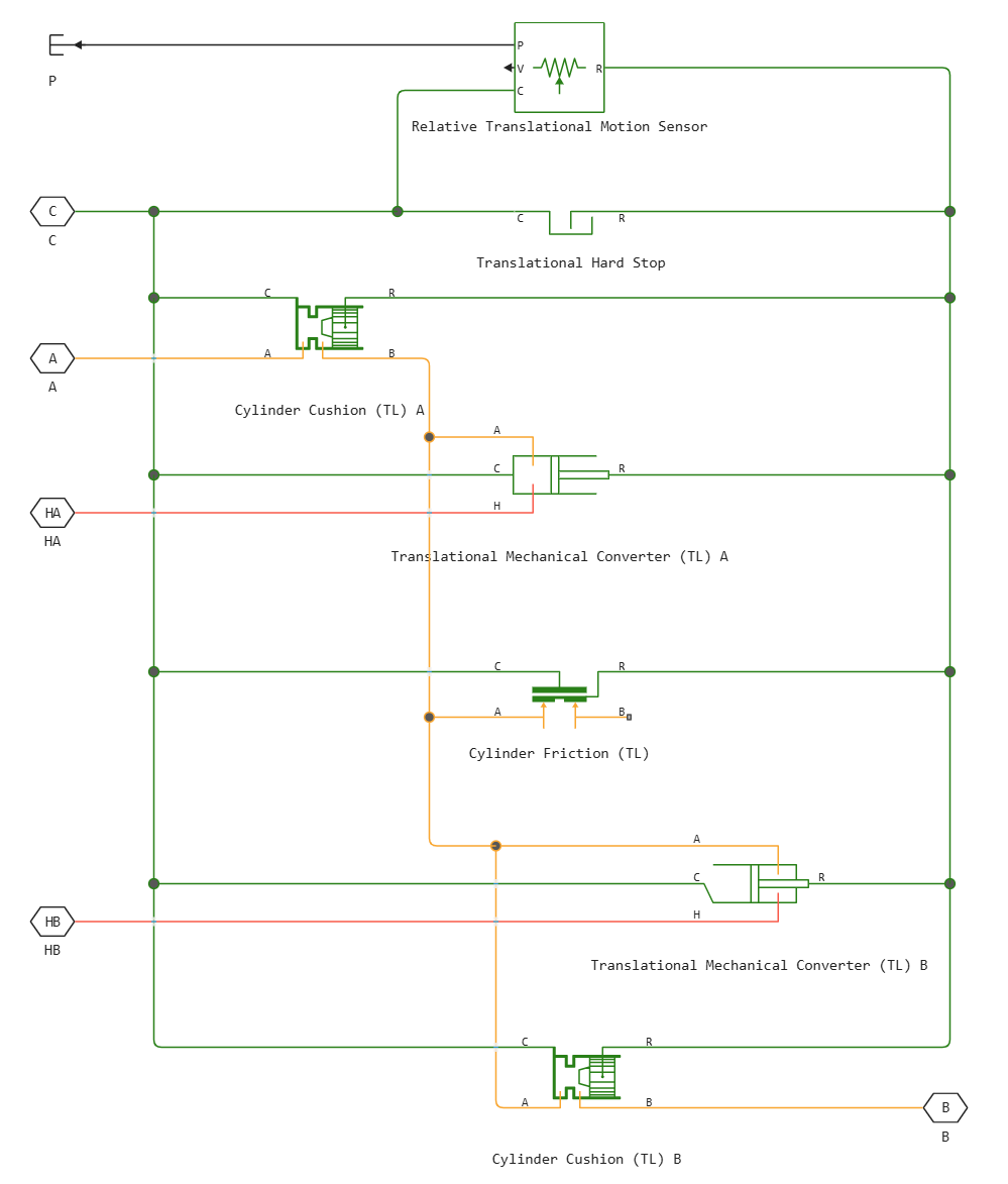
Block diagram
Block Double-Acting Actuator (TL) It consists of three library blocks Heat-conducting fluid and two library blocks Mechanics:
The structural diagram of the drive is shown in the diagram.
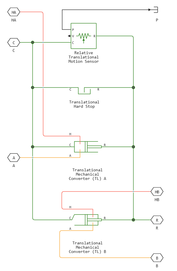
If you check the option boxes Cylinder friction, Cylinder A end cushioning or Cylinder B end cushioning, the block diagram also includes a block Cylinder Friction (TL) or two blocks Cylinder Cushion (TL).
Ports
Conserving
#
A
—
inlet for fluid flow into the chamber A
thermal liquid
Details
The thermal liquid port corresponding to the entrance to the chamber A.
| Program usage name |
|
#
B
—
inlet for fluid flow into the chamber B
thermal liquid
Details
The thermal liquid port corresponding to the entrance to the chamber B.
| Program usage name |
|
#
R
—
drive piston
translational mechanics
Details
Mechanical translational port corresponding to the drive piston.
| Program usage name |
|
#
C
—
drive housing
translational mechanics
Details
Mechanical translational port corresponding to the drive housing.
| Program usage name |
|
#
HA
—
heat flow through the chamber A
heat
Details
Thermal non-directional port corresponding to camera A.
| Program usage name |
|
#
HB
—
heat flow through the chamber B
heat
Details
Thermal non-directional port corresponding to camera B.
| Program usage name |
|
Output
#
p
—
piston position
scalar
Details
Piston position, in m.
| Data types |
|
| Complex numbers support |
I don’t |
Parameters
Actuator
# Same fluid on both sides — is the same fluid simulated in both chambers of the unit
Details
Whether the same fluid is simulated on both sides of the block. If the option is checked, then the properties of the liquid are distributed through the block. If unchecked, the chambers of the unit are connected to isolated networks of liquids with different properties.
| Default value |
|
| Program usage name |
|
| Evaluatable |
No |
#
Mechanical orientation —
the direction of movement of the piston
Pressure at A causes positive displacement of R relative to C | Pressure at A causes negative displacement of R relative to C
Details
Determines the direction of movement of the piston. Options to choose from:
-
Pressure at A causes positive displacement of R relative to C— the movement of the piston is positive if the volume of liquid in port A increases. This corresponds to the movement of the rod out of the cylinder. -
Pressure at A causes negative displacement of R relative to C— the movement of the piston is negative if the volume of liquid in port A increases. This corresponds to the movement of the rod inside the cylinder.
| Values |
|
| Default value |
|
| Program usage name |
|
| Evaluatable |
No |
#
Piston cross-sectional area in chamber A —
the cross-sectional area of the piston rod of the chamber A
m^2 | um^2 | mm^2 | cm^2 | km^2 | in^2 | ft^2 | yd^2 | mi^2 | ha | ac
Details
The cross-sectional area of the piston rod on the side of the chamber A.
| Units |
|
| Default value |
|
| Program usage name |
|
| Evaluatable |
Yes |
#
Piston cross-sectional area in chamber B —
the cross-sectional area of the piston rod of the chamber B
m^2 | um^2 | mm^2 | cm^2 | km^2 | in^2 | ft^2 | yd^2 | mi^2 | ha | ac
Details
The cross-sectional area of the piston rod on the side of the chamber B.
| Units |
|
| Default value |
|
| Program usage name |
|
| Evaluatable |
Yes |
#
Piston stroke —
stroke of the piston
m | um | mm | cm | km | in | ft | yd | mi | nmi
Details
The maximum possible displacement of the piston.
| Units |
|
| Default value |
|
| Program usage name |
|
| Evaluatable |
Yes |
#
Dead volume in chamber A —
the volume of liquid in the chamber A, at which the movement of the piston is 0
m^3 | um^3 | mm^3 | cm^3 | km^3 | ml | l | gal | igal | in^3 | ft^3 | yd^3 | mi^3
Details
The volume of liquid in the chamber A at the value of the piston displacement 0. This volume of liquid corresponds to the position of the piston, at which it is located at the top in relation to the end cap of the actuator.
| Units |
|
| Default value |
|
| Program usage name |
|
| Evaluatable |
Yes |
#
Dead volume in chamber B —
the volume of liquid in the chamber B, at which the movement of the piston is 0
m^3 | um^3 | mm^3 | cm^3 | km^3 | ml | l | gal | igal | in^3 | ft^3 | yd^3 | mi^3
Details
The volume of liquid in the chamber B at the value of the piston displacement 0. This volume of liquid corresponds to the position of the piston, at which it is located at the top in relation to the end cap of the actuator.
| Units |
|
| Default value |
|
| Program usage name |
|
| Evaluatable |
Yes |
#
Environment pressure specification —
the method of setting the ambient pressure
Atmospheric pressure | Specified pressure
Details
The method of setting the ambient pressure. Option Atmospheric pressure sets the ambient pressure equal to 0.101325 MPa.
| Values |
|
| Default value |
|
| Program usage name |
|
| Evaluatable |
No |
#
Environment pressure —
ambient pressure
Pa | uPa | hPa | kPa | MPa | GPa | kgf/m^2 | kgf/cm^2 | kgf/mm^2 | mbar | bar | kbar | atm | ksi | psi | mmHg | inHg
Details
User-defined ambient pressure.
Dependencies
To use this parameter, set for the parameter Environment pressure specification meaning Specified pressure.
| Units |
|
| Default value |
|
| Program usage name |
|
| Evaluatable |
Yes |
Hard Stop
#
Hard stop model —
choosing a rigid stop model
Stiffness and damping applied smoothly through transition region, damped rebound | Full stiffness and damping applied at bounds, undamped rebound | Full stiffness and damping applied at bounds, damped rebound | Based on coefficient of restitution
Details
Selecting a model for the force acting on the piston when it is in extreme positions. For more information, see the block Translational Hard Stop.
| Values |
|
| Default value |
|
| Program usage name |
|
| Evaluatable |
No |
#
Hard stop stiffness coefficient —
stiffness coefficient
N/m | mN/m | kN/m | MN/m | GN/m | kgf/m | lbf/ft | lbf/in
Details
The coefficient of piston stiffness.
| Units |
|
| Default value |
|
| Program usage name |
|
| Evaluatable |
Yes |
#
Hard stop damping coefficient —
damping coefficient
N*s/m | kgf*s/m | lbf*s/ft | lbf*s/in
Details
Piston damping coefficient.
| Units |
|
| Default value |
|
| Program usage name |
|
| Evaluatable |
Yes |
#
Transition region —
the range of action of the rigid stop model
m | um | mm | cm | km | in | ft | yd | mi | nmi
Details
The area of operation of the rigid stop. Outside of this range for the extreme positions of the piston Hard stop model it is not applied, and the additional force from the stop side does not act on the piston.
Dependencies
To use this parameter, set for the parameter Hard stop model meaning Stiffness and damping applied smoothly through transition region, damped rebound.
| Units |
|
| Default value |
|
| Program usage name |
|
| Evaluatable |
Yes |
# Coefficient of restitution — the ratio of the final and initial relative velocity between the rod and the stop after a collision
Details
The ratio of the final and initial relative velocity between the rod and the stop after the rod rebounds.
Dependencies
To use this parameter, set for the parameter Hard stop model meaning Based on coefficient of restitution.
| Default value |
|
| Program usage name |
|
| Evaluatable |
Yes |
#
Static contact speed threshold —
threshold value of the relative velocity between the rod and the stop before the collision
m/s | mm/s | cm/s | km/s | m/hr | km/hr | in/s | ft/s | mi/s | ft/min | mi/hr | kn
Details
The threshold value of the relative velocity between the rod and the stop before the collision. If the rod hits the housing at a speed lower than the value of this parameter, they remain in contact. Otherwise, the rod bounces off. To avoid simulating static contact between the rod and the housing, set this parameter to 0.
Dependencies
To use this parameter, set for the parameter Hard stop model meaning Based on coefficient of restitution.
| Units |
|
| Default value |
|
| Program usage name |
|
| Evaluatable |
Yes |
#
Static contact release force threshold —
the threshold value of the force required to transition from the contact state to the free state
N | nN | uN | mN | kN | MN | GN | dyn | lbf | kgf
Details
The minimum force required to remove the rod from the static contact state.
Dependencies
To use this parameter, set for the parameter Hard stop model meaning Based on coefficient of restitution.
| Units |
|
| Default value |
|
| Program usage name |
|
| Evaluatable |
Yes |
Cushion A
# Cylinder A end cushioning — option to simulate piston braking due to the action of a damper
Details
Whether the deceleration of the piston in its extreme positions is taken into account. For more information, see the see the block Cylinder Cushion (TL).
| Default value |
|
| Program usage name |
|
| Evaluatable |
No |
#
Cushion plunger cross-sectional area —
the cross-sectional area of the shock-absorbing plunger
m^2 | um^2 | mm^2 | cm^2 | km^2 | in^2 | ft^2 | yd^2 | mi^2 | ha | ac
Details
The cross-sectional area of the shock-absorbing plunger.
Dependencies
To use this option, check the box Cylinder A end cushioning.
| Units |
|
| Default value |
|
| Program usage name |
|
| Evaluatable |
Yes |
#
Cushion plunger length —
the length of the shock-absorbing plunger
m | um | mm | cm | km | in | ft | yd | mi | nmi
Details
The length of the shock-absorbing plunger.
Dependencies
To use this option, check the box Cylinder A end cushioning.
| Units |
|
| Default value |
|
| Program usage name |
|
| Evaluatable |
Yes |
#
Cushion orifice area —
the area of the opening between the damper chambers
m^2 | um^2 | mm^2 | cm^2 | km^2 | in^2 | ft^2 | yd^2 | mi^2 | ha | ac
Details
The area of the opening between the damper chambers.
Dependencies
To use this option, check the box Cylinder A end cushioning.
| Units |
|
| Default value |
|
| Program usage name |
|
| Evaluatable |
Yes |
#
Leakage area between plunger and cushion sleeve —
the area of the gap between the damper plunger and the bushing
m^2 | um^2 | mm^2 | cm^2 | km^2 | in^2 | ft^2 | yd^2 | mi^2 | ha | ac
Details
The area of the gap between the damper plunger and the bushing. The parameter supports computational stability of the simulation, ensuring continuity of the flow.
Dependencies
To use this option, check the box Cylinder A end cushioning.
| Units |
|
| Default value |
|
| Program usage name |
|
| Evaluatable |
Yes |
#
Check valve cracking pressure differential —
the pressure drop at which the check valve begins to open
Pa | uPa | hPa | kPa | MPa | GPa | kgf/m^2 | kgf/cm^2 | kgf/mm^2 | mbar | bar | kbar | atm | ksi | psi | mmHg | inHg
Details
The pressure at which the valve is triggered. When the pressure difference in port A and corresponds to or exceeds the value of this parameter, the non-return valve of the damper begins to open.
Dependencies
To use this option, check the box Cylinder A end cushioning.
| Units |
|
| Default value |
|
| Program usage name |
|
| Evaluatable |
Yes |
#
Check valve maximum pressure differential —
the pressure drop required to fully open the check valve
Pa | uPa | hPa | kPa | MPa | GPa | kgf/m^2 | kgf/cm^2 | kgf/mm^2 | mbar | bar | kbar | atm | ksi | psi | mmHg | inHg
Details
The maximum pressure drop of the damper check valve. This parameter sets the upper pressure limit so that the system pressure remains realistic.
Dependencies
To use this option, check the box Cylinder A end cushioning.
| Units |
|
| Default value |
|
| Program usage name |
|
| Evaluatable |
Yes |
#
Check valve maximum area —
the area of the fully open check valve
m^2 | um^2 | mm^2 | cm^2 | km^2 | in^2 | ft^2 | yd^2 | mi^2 | ha | ac
Details
The cross-sectional area of the non-return valve opening in the fully open position.
Dependencies
To use this option, check the box Cylinder A end cushioning.
| Units |
|
| Default value |
|
| Program usage name |
|
| Evaluatable |
Yes |
#
Check valve leakage area —
leakage area with the check valve fully closed
m^2 | um^2 | mm^2 | cm^2 | km^2 | in^2 | ft^2 | yd^2 | mi^2 | ha | ac
Details
The total area of possible leaks when the check valve is fully closed. Any area less than this value increases smoothly to the specified leakage area. This value contributes to computational robustness by maintaining continuity of flow.
Dependencies
To use this option, check the box Cylinder A end cushioning.
| Units |
|
| Default value |
|
| Program usage name |
|
| Evaluatable |
Yes |
# Smoothing factor — numerical smoothing factor
Details
The continuous smoothing coefficient, which ensures smooth opening by correcting for the valve characteristics in the almost open and almost closed positions. Set a non-zero value less than one to increase the stability of the simulation.
Dependencies
To use this option, check the box Cylinder A end cushioning.
| Default value |
|
| Program usage name |
|
| Evaluatable |
Yes |
Cushion B
# Cylinder B end cushioning — the option of modeling piston braking due to the action of a damper
Details
Whether the deceleration of the piston in its extreme positions is taken into account. For more information, see the section Cylinder Cushion (TL).
| Default value |
|
| Program usage name |
|
| Evaluatable |
No |
#
Cushion plunger cross-sectional area —
the cross-sectional area of the shock-absorbing plunger
m^2 | um^2 | mm^2 | cm^2 | km^2 | in^2 | ft^2 | yd^2 | mi^2 | ha | ac
Details
The cross-sectional area of the shock-absorbing plunger.
Dependencies
To use this option, check the box Cylinder B end cushioning.
| Units |
|
| Default value |
|
| Program usage name |
|
| Evaluatable |
Yes |
#
Cushion plunger length —
the length of the shock-absorbing plunger
m | um | mm | cm | km | in | ft | yd | mi | nmi
Details
The length of the shock-absorbing plunger.
Dependencies
To use this option, check the box Cylinder B end cushioning.
| Units |
|
| Default value |
|
| Program usage name |
|
| Evaluatable |
Yes |
#
Cushion orifice area —
the area of the opening between the damper chambers
m^2 | um^2 | mm^2 | cm^2 | km^2 | in^2 | ft^2 | yd^2 | mi^2 | ha | ac
Details
The area of the opening between the damper chambers.
Dependencies
To use this option, check the box Cylinder B end cushioning.
| Units |
|
| Default value |
|
| Program usage name |
|
| Evaluatable |
Yes |
#
Leakage area between plunger and cushion sleeve —
the area of the gap between the damper plunger and the bushing
m^2 | um^2 | mm^2 | cm^2 | km^2 | in^2 | ft^2 | yd^2 | mi^2 | ha | ac
Details
The area of the gap between the damper plunger and the bushing. The parameter supports computational stability of the simulation, ensuring continuity of the flow.
Dependencies
To use this option, check the box Cylinder B end cushioning.
| Units |
|
| Default value |
|
| Program usage name |
|
| Evaluatable |
Yes |
#
Check valve cracking pressure differential —
the pressure drop at which the check valve begins to open
Pa | uPa | hPa | kPa | MPa | GPa | kgf/m^2 | kgf/cm^2 | kgf/mm^2 | mbar | bar | kbar | atm | ksi | psi | mmHg | inHg
Details
The pressure at which the valve is triggered. When the pressure difference in port B and corresponds to or exceeds the value of this parameter, the non-return valve of the damper begins to open.
Dependencies
To use this option, check the box Cylinder B end cushioning.
| Units |
|
| Default value |
|
| Program usage name |
|
| Evaluatable |
Yes |
#
Check valve maximum pressure differential —
the pressure drop required to fully open the check valve
Pa | uPa | hPa | kPa | MPa | GPa | kgf/m^2 | kgf/cm^2 | kgf/mm^2 | mbar | bar | kbar | atm | ksi | psi | mmHg | inHg
Details
The maximum pressure drop of the damper check valve. This parameter sets the upper pressure limit so that the system pressure remains realistic.
Dependencies
To use this option, check the box Cylinder B end cushioning.
| Units |
|
| Default value |
|
| Program usage name |
|
| Evaluatable |
Yes |
#
Check valve maximum area —
the area of the fully open check valve
m^2 | um^2 | mm^2 | cm^2 | km^2 | in^2 | ft^2 | yd^2 | mi^2 | ha | ac
Details
The cross-sectional area of the non-return valve opening in the fully open position.
Dependencies
To use this option, check the box Cylinder B end cushioning.
| Units |
|
| Default value |
|
| Program usage name |
|
| Evaluatable |
Yes |
#
Check valve leakage area —
leakage area with the check valve fully closed
m^2 | um^2 | mm^2 | cm^2 | km^2 | in^2 | ft^2 | yd^2 | mi^2 | ha | ac
Details
The total area of possible leaks when the check valve is fully closed. Any area less than this value increases smoothly to the specified leakage area. This value contributes to computational robustness by maintaining continuity of flow.
Dependencies
To use this option, check the box Cylinder B end cushioning.
| Units |
|
| Default value |
|
| Program usage name |
|
| Evaluatable |
Yes |
# Smoothing factor — numerical smoothing factor
Details
The continuous smoothing coefficient, which ensures smooth opening by correcting for the valve characteristics in the almost open and almost closed positions. Set a non-zero value less than one to increase the stability of the simulation.
Dependencies
To use this option, check the box Cylinder B end cushioning.
| Default value |
|
| Program usage name |
|
| Evaluatable |
Yes |
Friction
# Cylinder friction — option to simulate friction during piston movement
Details
Whether the friction of the piston is taken into account during movement. The friction force of the block consists of the Shtribek force, Coulomb force and viscosity. For more information, see the section Cylinder Friction (TL).
| Default value |
|
| Program usage name |
|
| Evaluatable |
No |
# Breakaway to Coulomb friction force ratio — the ratio of the separation force to the Coulomb friction force
Details
The ratio of the separation force to the Coulomb friction force.
Dependencies
To use this option, check the box Cylinder friction.
| Default value |
|
| Program usage name |
|
| Evaluatable |
Yes |
#
Breakaway friction velocity —
threshold of movement against the friction force
m/s | mm/s | cm/s | km/s | m/hr | km/hr | in/s | ft/s | mi/s | ft/min | mi/hr | kn
Details
The threshold value of the speed at which movement begins against the friction force.
Dependencies
To use this option, check the box Cylinder friction.
| Units |
|
| Default value |
|
| Program usage name |
|
| Evaluatable |
Yes |
#
Preload force —
the initial force in the cylinder, which occurs during the assembly of the seal, N
N | nN | uN | mN | kN | MN | GN | dyn | lbf | kgf
Details
The initial force in the cylinder under the action of the seal assembly. The block uses this parameter to calculate the Coulomb friction force.
Dependencies
To use this option, check the box Cylinder friction.
| Units |
|
| Default value |
|
| Program usage name |
|
| Evaluatable |
Yes |
#
Coulomb friction force coefficient —
coefficient of Coulomb friction force
m^2 | um^2 | mm^2 | cm^2 | km^2 | in^2 | ft^2 | yd^2 | mi^2 | ha | ac | N/Pa
Details
The coefficient of Coulomb friction force.
Dependencies
To use this option, check the box Cylinder friction.
| Units |
|
| Default value |
|
| Program usage name |
|
| Evaluatable |
Yes |
#
Viscous friction coefficient —
coefficient of viscous friction
N*s/m | kgf*s/m | lbf*s/ft | lbf*s/in
Details
Coefficient of viscous friction.
Dependencies
To use this option, check the box Cylinder friction.
| Units |
|
| Default value |
|
| Program usage name |
|
| Evaluatable |
Yes |
Initial Conditions
#
Initial piston displacement from chamber A cap —
the initial position of the piston relative to the chamber cover A
m | um | mm | cm | km | in | ft | yd | mi | nmi
Details
The position of the piston relative to the chamber cover A at the beginning of the simulation.
| Units |
|
| Default value |
|
| Program usage name |
|
| Evaluatable |
Yes |
# Fluid dynamic compressibility — the option of modeling the compressibility of a liquid
Details
Accounting for changes in the density of a liquid due to its compressibility. If the check box is selected Fluid dynamic compressibility, then the changes associated with the mass flow rate of the fluid in the block are calculated in addition to the density changes associated with pressure changes. In the library Isothermal liquid all blocks calculate density as a function of pressure.
| Default value |
|
| Program usage name |
|
| Evaluatable |
No |
#
Initial liquid pressure in chamber A —
initial fluid pressure for compressible fluids in the chamber A
Pa | uPa | hPa | kPa | MPa | GPa | kgf/m^2 | kgf/cm^2 | kgf/mm^2 | mbar | bar | kbar | atm | ksi | psi | mmHg | inHg
Details
The initial fluid pressure for compressible fluids in the chamber A.
Dependencies
To use this option, check the box Fluid dynamic compressibility.
| Units |
|
| Default value |
|
| Program usage name |
|
| Evaluatable |
Yes |
#
Initial liquid pressure in chamber B —
initial fluid pressure for compressible fluids in the chamber B
Pa | uPa | hPa | kPa | MPa | GPa | kgf/m^2 | kgf/cm^2 | kgf/mm^2 | mbar | bar | kbar | atm | ksi | psi | mmHg | inHg
Details
The initial fluid pressure for compressible fluids in the chamber B.
Dependencies
To use this option, check the box Fluid dynamic compressibility.
| Units |
|
| Default value |
|
| Program usage name |
|
| Evaluatable |
Yes |
#
Initial liquid temperature in chamber A —
initial temperature for compressible liquids in the chamber A
K | degC | degF | degR | deltaK | deltadegC | deltadegF | deltadegR
Details
The initial liquid temperature for compressible liquids in the chamber is A.
Dependencies
To use this option, check the box Fluid dynamic compressibility.
| Units |
|
| Default value |
|
| Program usage name |
|
| Evaluatable |
Yes |
#
Initial liquid temperature in chamber B —
initial temperature for compressible liquids in the chamber B
K | degC | degF | degR | deltaK | deltadegC | deltadegF | deltadegR
Details
The initial liquid temperature for compressible liquids in the chamber is B.
Dependencies
To use this option, check the box Fluid dynamic compressibility.
| Units |
|
| Default value |
|
| Program usage name |
|
| Evaluatable |
Yes |