Cylinder Cushion (TL)
Hydraulic cylinder damper in a thermal liquid network.
blockType: EngeeFluids.ThermalLiquid.Actuators.Auxiliary.CylinderCushion
|
Path in the library: |

Description
The Cylinder Cushion (TL) unit is a hydraulic cylinder damper in a thermal liquid network. The damper slows the cylinder rod as it approaches the end of its stroke, limiting the flow of fluid exiting the piston cavity. The figure below shows a typical damper design [1].

As the piston moves toward the cap, which is on the left in the figure, the damper sleeve, or plunger, enters a mating hole in the cap (damper cavity) and provides additional resistance to the fluid leaving the cylinder working cavity. Piston deceleration begins when the plunger enters the damper cavity in the cap and blocks the main fluid outlet. In this condition, fluid flows through the throttle valve and the minimum clearance. The valve limits the flow of fluid exiting the operating cavity and brakes the piston.
The hydraulic cylinder damper consists of two orifices, variable and constant cross-sections, and a check valve. The variable bore represents the variable clearance between the plug and the notch in the end cap. The constant cross-section port is a throttle in the channel connecting the damper cavity to the piston cavity. The check valve allows flow between the damper cavity and the piston cavity only when the piston is extended.
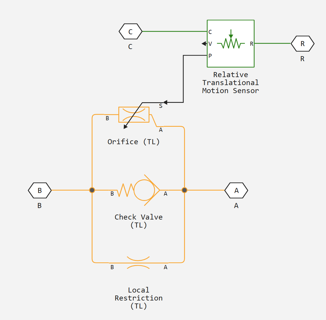
The Cylinder Cushion (TL) assembly is a composite component consisting of the following blocks:
-
Block Local Restriction (TL) models the throttle valve.
-
Block Check Valve (TL) models the check valve.
-
Block Orifice (TL) models the variable clearance between plug and end cap.
-
Block Absolute Translational Motion Sensor converts the distance between the plug and the cavity in the end cap into a physical signal. This signal controls the degree of opening of the variable clearance.
The Cylinder Cushion (TL) block can be used to model hydraulic actuators. A single-acting or double-acting hydraulic actuator can include dampers to slow the piston near the ends of the stroke. The damper prevents hard shocks when the piston is stopped by the end caps.
Ports A and B are non-directional thermal liquid ports associated with the fluid supply and piston cavity, respectively. Port R is a mechanical non-directional port associated with the piston plunger. Port C is a mechanical non-directional port associated with the clamping structure of the cylinder. The block dampens the flow from port B to port A. The check valve in the block is orientated from port A to port B.
Variable port area
In a variable orifice block, it is assumed that when the plunger is away from the cover, the cross section of the main fluid path is open and its area is , where is the diameter of the round plunger. When the plunger is in the cap, the orifice is completely closed and the orifice area is equal to the leakage area. When the plunger moves towards the cap, fluid flows through the radial gap from the cylinder cavity into the reciprocal hole on the cap. It is assumed that the orifice area varies linearly with piston movement between the maximum area and the leakage area. The orifice area for a given piston position is
where
-
- is the bore area for the given piston position;
-
- is the leakage area between plunger and cushion sleeve, the value of the Leakage area between plunger and cushion sleeve parameters;
-
- maximum bore size, which is equal to the value of the Cushion plunger cross-sectional area parameter;
-
- piston position. Piston initial displacement ; the value of the Actuator piston initial displacement parameters;
-
- has a value of
1when the Actuator mechanical orientation parameter is set toPressure at A causes positive displacement of R relative to C, and-1when the Actuator mechanical orientation parameter is set toPressure at A causes negative displacement of R relative to C; -
- length of the cushioning plunger, the value of the Cushion plunger length parameters;
-
- cushion plunger diameter, the value of the Cushion plunger diameter parameter.
Numerical smoothing of area and pressure values
The numerical stability of the simulation is maintained by adjusting the Smoothing factor parameters. If the Smoothing factor parameters are not zero, the orifice area and check valve control pressure are smoothed. The Leakage area between plunger and cushion sleeve and Cushion plunger cross-sectional area parameters are also smooth. The control pressure of the valve is continuously variable between the parameters Check valve cracking pressure differential and Check valve maximum pressure differential.
Ports
Conserving
#
A
—
inlet opening
thermal liquid
Details
The thermal liquid port corresponding to the entrance to the damper cavity.
| Program usage name |
|
#
C
—
hull
translational mechanics
Details
A mechanical progressive port corresponding to the support structure of a hydraulic cylinder.
| Program usage name |
|
#
B
—
outlet opening
thermal liquid
Details
The thermal liquid port corresponding to the outlet to the piston cavity.
| Program usage name |
|
#
R
—
stem
translational mechanics
Details
A mechanical progressive port corresponding to the speed and piston force of a hydraulic cylinder.
| Program usage name |
|
Parameters
Cushion Plunger
#
Cushion plunger cross-sectional area —
cross-sectional area of the damping plug
m^2 | um^2 | mm^2 | cm^2 | km^2 | in^2 | ft^2 | yd^2 | mi^2 | ha | ac
Details
Cross-sectional area of the damping plug. The area is equal to , where is the diameter of the round plug.
| Units |
|
| Default value |
|
| Program usage name |
|
| Evaluatable |
Yes |
#
Cushion plunger length —
damping plug length
m | um | mm | cm | km | in | ft | yd | mi | nmi
Details
Length of the damping plug.
| Units |
|
| Default value |
|
| Program usage name |
|
| Evaluatable |
Yes |
#
Initial actuator piston displacement —
initial piston displacement
m | um | mm | cm | km | in | ft | yd | mi | nmi
Details
The offset of the piston in the cylinder at the start of the simulation. This displacement defines the initial area of the variable bore, which simulates the variable clearance between the ram and the end cap.
Dependencies
If the Actuator mechanical orientation parameters are set to `Pressure at A causes positive displacement of R relative to C', the value of the initial piston displacement must be greater than or equal to zero.
If the Actuator mechanical orientation parameters are set to `Pressure at A causes negative displacement of R relative to C', the value of the initial piston displacement must be less than or equal to zero.
| Units |
|
| Default value |
|
| Program usage name |
|
| Evaluatable |
Yes |
#
Actuator mechanical orientation —
piston displacement direction
Pressure at A causes positive displacement of R relative to C | Pressure at A causes negative displacement of R relative to C
Details
Direction of piston displacement of the connected actuator unit. If this parameter is set to Pressure at A causes positive displacement of R relative to C, the piston extends at positive displacement of R to C. If this parameter is set to Pressure at A causes negative displacement of R relative to C, the piston retracts at positive R to C.
| Values |
|
| Default value |
|
| Program usage name |
|
| Evaluatable |
No |
#
Piston cross-sectional area —
piston bore cross-sectional area
m^2 | um^2 | mm^2 | cm^2 | km^2 | in^2 | ft^2 | yd^2 | mi^2 | ha | ac
Details
Cross-sectional area of the hydraulic cylinder piston bore.
| Units |
|
| Default value |
|
| Program usage name |
|
| Evaluatable |
Yes |
Valves
#
Cushion orifice area —
orifice area of the butterfly valve
m^2 | um^2 | mm^2 | cm^2 | km^2 | in^2 | ft^2 | yd^2 | mi^2 | ha | ac
Details
The constant area of the throttle valve orifice through which fluid flows from the piston cavity when the plunger is inside the damper cavity.
| Units |
|
| Default value |
|
| Program usage name |
|
| Evaluatable |
Yes |
#
Leakage area between plunger and cushion sleeve —
total leakage area when the plunger is inside the cover hole
m^2 | um^2 | mm^2 | cm^2 | km^2 | in^2 | ft^2 | yd^2 | mi^2 | ha | ac
Details
The total area of possible leakage when the plunger is inside the damper cavity. When the piston movement is less than or equal to the Cushion plunger length parameters, the area of the variable hole modelling the gap between the plunger and the cap is equal to the value of this parameter.
| Units |
|
| Default value |
|
| Program usage name |
|
| Evaluatable |
Yes |
#
Check valve cracking pressure differential —
differential pressure at which the check valve starts to open
Pa | uPa | hPa | kPa | MPa | GPa | kgf/m^2 | kgf/cm^2 | kgf/mm^2 | mbar | bar | kbar | atm | ksi | psi | mmHg | inHg
Details
Minimum differential pressure across the check valve at which the check valve begins to open. The check valve allows fluid to flow freely from the damper cavity to the piston cavity, but does not allow fluid to flow in the opposite direction.
| Units |
|
| Default value |
|
| Program usage name |
|
| Evaluatable |
Yes |
#
Check valve maximum pressure differential —
pressure drop required to fully open the check valve
Pa | uPa | hPa | kPa | MPa | GPa | kgf/m^2 | kgf/cm^2 | kgf/mm^2 | mbar | bar | kbar | atm | ksi | psi | mmHg | inHg
Details
The pressure drop across the check valve required for the check valve to fully open. The value of this parameter must be greater than the Check valve cracking pressure differential. The check valve allows fluid to flow freely from the damper cavity to the piston cavity, but does not allow fluid to flow in the opposite direction.
| Units |
|
| Default value |
|
| Program usage name |
|
| Evaluatable |
Yes |
#
Check valve maximum area —
area of fully open check valve
m^2 | um^2 | mm^2 | cm^2 | km^2 | in^2 | ft^2 | yd^2 | mi^2 | ha | ac
Details
The cross-sectional area of the check valve orifice in the fully open position.
| Units |
|
| Default value |
|
| Program usage name |
|
| Evaluatable |
Yes |
#
Check valve leakage area —
total leakage area with fully closed check valve
m^2 | um^2 | mm^2 | cm^2 | km^2 | in^2 | ft^2 | yd^2 | mi^2 | ha | ac
Details
Total possible leakage area with fully closed non-return valve.
| Units |
|
| Default value |
|
| Program usage name |
|
| Evaluatable |
Yes |
# Smoothing factor — numerical smoothing factor
Details
Continuous smoothing factor that provides smooth opening by correcting the valve characteristic in the nearly open and nearly closed positions. Set a non-zero value less than one to increase the stability of the simulation in these modes.
| Default value |
|
| Program usage name |
|
| Evaluatable |
Yes |