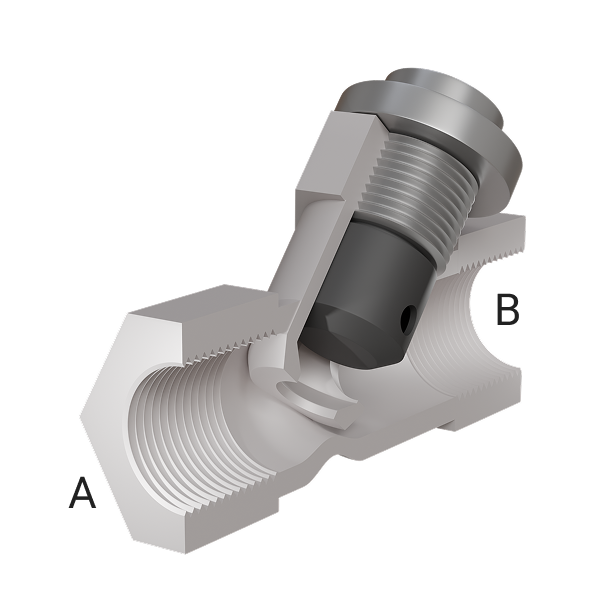
Check Valve (TL)
A check valve in a thermal liquid network.
blockType: EngeeFluids.ThermalLiquid.Valves.DirectionalControl.Check
|
Path in the library: |

Description
The Check Valve (IL) unit is a check valve in a thermal liquid network. A check valve is a proportional valve that closes when the pressure difference between its ports falls below a threshold value called actuation pressure. Check valves are often used in backflow prevention devices, such as in public water supplies, where contaminated water downstream of the water supply must not be returned upstream. This unit does not involve a specific shut-off mechanism such as a ball, disc or diaphragm. Flow is only possible in the direction from port A to port B.
The valve opens when its differential pressure rises above the specified actuation pressure. When the differential pressure reaches the maximum value specified in the block, the valve is fully open and its opening area no longer increases with increasing pressure. The flow rate through the valve is never zero because a small leakage area remains when the pressure drops below the actuation pressure.
The opening area of the valve depends linearly on the differential pressure.
There are two options for controlling the valve:
-
If the Pressure control specification parameters are set to
Pressure differential, the control pressure is the differential pressure between ports A and B. The valve starts to open when reaches or exceeds the value of Cracking pressure differential. -
If the Pressure control specification parameters are set to
Pressure at port A, the control pressure is the pressure differential between port A and atmospheric pressure. The valve starts to open when reaches or exceeds the Cracking pressure (gauge) value.
The linear parameterization of the valve cross-section is as follows
where the normalised pressure is
For cases where the valve is in the nearly open or nearly closed positions, the numerical stability of the simulation is controlled by the Smoothing factor parameters. If the Smoothing factor parameters are not zero, the control pressure changes smoothly between and .
The mass flow rate through the valve is calculated as follows:
where
-
- is the flow coefficient, the value of the Discharge coefficient parameters;
-
- instantaneous valve opening area;
-
- the value of the Cross-sectional area at ports A and B parameters;
-
- is the average density of the fluid;
-
- pressure difference in the valve .
Critical pressure drop, - pressure drop determined from the value of the critical Reynolds number , given by the Critical Reynolds number parameters, which is the transition point between laminar and turbulent flow regimes:
Pressure loss shows the pressure drop in the valve due to the reduction in valve area and is calculated as:
Pressure recovery describes the positive change in valve pressure due to an increase in area. To disregard pressure recovery, uncheck the Pressure recovery box. In this case the pressure loss .
Mass conservation
Mass conservation equation:
Where and are the mass flow rate at port A and B respectively.
Energy conservation
The valve is an adiabatic component. There is no heat exchange between the fluid and the valve wall. No work is done on the fluid as it passes through the valve. With these assumptions, energy can only flow in and out of the valve by convection through ports A and B. According to the principle of conservation of energy, the sum of the energy flows through the ports is always zero:
where and are the energy flow into the valve through ports A and B respectively.
Opening dynamics
The opening and closing dynamics of the valve can be optionally modelled in the block, whereby a delay is added to the signal pressure. In this case, the dynamic signal pressure is used instead of , if the opening dynamics are not taken into account, is the steady-state pressure. The derivative of the dynamic control pressure is calculated from the Opening time constant :
By default, the Opening dynamics checkbox is unchecked.
Parameters
Parameters
#
Pressure control specification —
differential pressure used to control the valve
Pressure differential | Pressure at port A
Details
Defines the control pressure. The `Pressure differential' value defines the control pressure as the pressure difference between ports A and B. The `Pressure at port A' value defines the control pressure as the difference between the pressure at port A and the atmospheric pressure.
| Values |
|
| Default value |
|
| Program usage name |
|
| Evaluatable |
No |
#
Cracking pressure (gauge) —
overpressure response
Pa | uPa | hPa | kPa | MPa | GPa | kgf/m^2 | kgf/cm^2 | kgf/mm^2 | mbar | bar | kbar | atm | ksi | psi | mmHg | inHg
Details
The overpressure above which the valve is actuated. This pressure is set when the control pressure is the differential pressure between port A and atmospheric pressure.
Dependencies
To use this parameter, set the Opening pressure specification parameters to `Pressure at port A'.
| Units |
|
| Default value |
|
| Program usage name |
|
| Evaluatable |
Yes |
#
Cracking pressure differential —
actuation pressure
Pa | uPa | hPa | kPa | MPa | GPa | kgf/m^2 | kgf/cm^2 | kgf/mm^2 | mbar | bar | kbar | atm | ksi | psi | mmHg | inHg
Details
The pressure above which the valve is actuated. This pressure is set when the control pressure is the differential pressure between ports A and B.
Dependencies
To use this parameter, set the Opening pressure specification parameters to `Pressure differential'.
| Units |
|
| Default value |
|
| Program usage name |
|
| Evaluatable |
Yes |
#
Maximum opening pressure (gauge) —
overpressure for fully open valve
Pa | uPa | hPa | kPa | MPa | GPa | kgf/m^2 | kgf/cm^2 | kgf/mm^2 | mbar | bar | kbar | atm | ksi | psi | mmHg | inHg
Details
The overpressure at which the valve is fully open.
Dependencies
To use this parameter, set the Opening pressure specification parameters to `Pressure at port A'.
| Units |
|
| Default value |
|
| Program usage name |
|
| Evaluatable |
Yes |
#
Maximum opening pressure differential —
Pressure drop for fully open valve
Pa | uPa | hPa | kPa | MPa | GPa | kgf/m^2 | kgf/cm^2 | kgf/mm^2 | mbar | bar | kbar | atm | ksi | psi | mmHg | inHg
Details
The differential pressure at which the valve is fully open.
Dependencies
To use this parameter, set the Opening pressure specification parameters to `Pressure differential'.
| Units |
|
| Default value |
|
| Program usage name |
|
| Evaluatable |
Yes |
#
Maximum opening area —
fully open valve area
m^2 | um^2 | mm^2 | cm^2 | km^2 | in^2 | ft^2 | yd^2 | mi^2 | ha | ac
Details
The cross-sectional area of the valve bore in the fully open position.
| Units |
|
| Default value |
|
| Program usage name |
|
| Evaluatable |
Yes |
#
Leakage area —
valve clearance area in fully closed position
m^2 | um^2 | mm^2 | cm^2 | km^2 | in^2 | ft^2 | yd^2 | mi^2 | ha | ac
Details
The sum of all clearances when the valve is in the fully closed position. Any area less than this value equates to the specified leakage area. This parameter contributes to the stability of the numerical solution by maintaining flow continuity.
| Units |
|
| Default value |
|
| Program usage name |
|
| Evaluatable |
Yes |
# Smoothing factor — numerical smoothing factor
Details
Continuous smoothing factor that provides smooth opening by correcting the valve characteristic in the nearly open and nearly closed positions. Set a non-zero value less than one to increase the stability of the simulation in these modes.
| Default value |
|
| Program usage name |
|
| Evaluatable |
Yes |
#
Cross-sectional area at ports A and B —
area at the inlet or outlet of the valve
m^2 | um^2 | mm^2 | cm^2 | km^2 | in^2 | ft^2 | yd^2 | mi^2 | ha | ac
Details
The cross-sectional area at ports A and B. This area is used to calculate the mass flow rate through the valve.
| Units |
|
| Default value |
|
| Program usage name |
|
| Evaluatable |
Yes |
# Discharge coefficient — flow coefficient
Details
The correction factor is the ratio of the actual mass flow rate to the theoretical mass flow rate through the valve.
| Default value |
|
| Program usage name |
|
| Evaluatable |
Yes |
# Critical Reynolds number — upper limit of Reynolds number for laminar flow
Details
Upper Reynolds number limit for laminar flow through the valve.
| Default value |
|
| Program usage name |
|
| Evaluatable |
Yes |