Delta Sigma Modulator
An ADC based on a sigma-delta modulator.
blockType: SubSystem
|
Path in the library: |
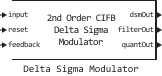
Description
Block Delta Sigma Modulator Simulates an ADC based on a sigma-delta modulator using four different architecture types:
-
cascade of integrators with feedback (CIFB);
-
cascade of resonators with feedback (CRFB);
-
cascade of integrators with direct connection (CIFF);
-
cascade of resonators with direct connection (CRFF).
Sigma-delta modulators of orders from the first to the sixth can be modeled. The block also allows you to design cascading structures such as multi-stage noise filtering and transformation (MASH) and a stable MASH architecture (S-MASH). In addition, the simulation of noise caused by the characteristics of the circuit components is supported. You can plot the noise transfer function and the signal transfer function, as well as estimate the signal-to-noise ratio.
Ports
Input
#
input
—
analog input signal
scalar
Details
An analog input signal specified as a scalar.
| Data types |
|
| Complex numbers support |
No |
#
reset
—
resetting the sigma-delta modulator
scalar
Details
Reset signal for the block Delta Sigma Modulator, set as a scalar.
| Data types |
|
| Complex numbers support |
No |
#
feedback
—
the output signal of the next stage
scalar
Details
The output signal of the next stage. Use this port to feed the output signal back to the unit when simulating a multi-stage sigma-delta modulator. If there is no feedback from the next stage, connect this port to the unit. Ground.
Use this port to build cascaded sigma-delta modulator structures such as MASH and S-MASH.
| Data types |
|
| Complex numbers support |
No |
Output
#
dsmOut
—
digital output signal
scalar
Details
A digital output signal returned as a scalar.
| Data types |
|
| Complex numbers support |
No |
#
filterOut
—
contour filter output signal
scalar
Details
The output signal of the contour filter inside the sigma-delta modulator, returned as a scalar.
| Data types |
|
| Complex numbers support |
No |
#
quantOut
—
the output signal of the quantizer
scalar
Details
The output signal of the quantizer inside the sigma-delta modulator, returned as a scalar. If this port is not in use, connect it to the unit. Terminator.
If the feedback port is not used, the values on the quantOut and dsmOut ports match.
Use this port to build cascaded sigma-delta modulator structures such as MASH and S-MASH.
| Data types |
|
| Complex numbers support |
No |
Parameters
Parameters
Configuration
#
Architecture —
sigma-delta modulator architecture
CIFB | CRFB | CIFF | CRFF
Details
Sigma-delta modulator architecture, specified by one of the following values:
-
CIFB— cascade of integrators with feedback; -
CRFB— cascade of resonators with feedback; -
CIFF— cascade of integrators with direct connection; -
CRFF— cascade of resonators with direct connection.
| Values |
|
| Default value |
|
| Program usage name |
|
| Tunable |
No |
| Evaluatable |
Yes |
#
Order —
sigma-delta modulator order
1st order | 2nd order | 3rd order | 4th order | 5th order | 6th order
Details
The order of the sigma-delta modulator. You can choose the order from first to sixth.
| Values |
|
| Default value |
|
| Program usage name |
|
| Tunable |
No |
| Evaluatable |
Yes |
Input parameters
# System bandwidth (Hz) — The bandwidth of the sigma-delta modulator system
Details
The bandwidth of the sigma-delta modulator system, specified as a non-negative real scalar.
| Default value |
|
| Program usage name |
|
| Tunable |
No |
| Evaluatable |
Yes |
# OSR — the ratio of the sigma-delta modulator sampling rate to the Nyquist frequency
Details
The ratio of the sigma-delta modulator sampling rate to the Nyquist frequency, given as a non-negative real scalar. The high oversampling coefficient allows the use of a less complex spectrum overlay protection filter and reduces quantization noise in the operating frequency band.
| Default value |
|
| Program usage name |
|
| Tunable |
No |
| Evaluatable |
Yes |
# Sampling frequency (Hz) — Sampling rate of the sigma-delta modulator
Details
The sampling rate of the sigma-delta modulator. This parameter is read-only and is calculated based on the parameters System bandwidth (Hz) and OSR.
| Default value |
|
| Program usage name |
|
| Tunable |
No |
| Evaluatable |
Yes |
# Number levels — number of quantizer levels in the sigma-delta modulator
Details
The number of quantizer levels in the sigma-delta modulator, set as a positive integer.
| Default value |
|
| Program usage name |
|
| Tunable |
No |
| Evaluatable |
Yes |
# Quantizer output — the range of output values of the quantizer
Details
The range of output values of the quantizer in the sigma-delta modulator architecture, returned as a vector of real elements. This parameter is read-only.
| Default value |
|
| Program usage name |
|
| Tunable |
No |
| Evaluatable |
Yes |
# Enable dynamic range scaling — enabling scaling of the dynamic range of coefficients
Details
Select this option to enable scaling of the dynamic range of coefficients. This prevents premature saturation of internal states.
Dependencies
To use this option, uncheck the box. Use custom coefficient values.
| Default value |
|
| Program usage name |
|
| Tunable |
No |
| Evaluatable |
Yes |
# Use custom coefficient values — the ability to use custom coefficient values 'a', 'g', 'b' and 'c'
Details
Select this checkbox to set custom parameter values. Coefficient 'a', Coefficient 'g', Coefficient 'b' and Coefficient 'c'.
| Default value |
|
| Program usage name |
|
| Tunable |
No |
| Evaluatable |
Yes |
Custom coefficients
# Coefficient 'a' — feedback coefficients from the quantizer or direct coupling to the quantizer
Details
Feedback coefficients from the quantizer or direct coupling to the quantizer, specified as a vector of real elements.
Dependencies
To use this option, check the box Use custom coefficient values.
| Default value |
|
| Program usage name |
|
| Tunable |
No |
| Evaluatable |
Yes |
# Coefficient 'g' — resonator coefficients
Details
Resonator coefficients, defined as a vector of real elements.
Dependencies
To use this option, check the box Use custom coefficient values.
| Default value |
|
| Program usage name |
|
| Tunable |
No |
| Evaluatable |
Yes |
# Coefficient 'b' — signal transmission coefficients from the modulator input to each integrator
Details
The coefficients of signal transmission from the modulator input to each integrator, specified as a vector of real elements.
Dependencies
To use this option, check the box Use custom coefficient values.
| Default value |
|
| Program usage name |
|
| Tunable |
No |
| Evaluatable |
Yes |
# Coefficient 'c' — inter-stage integrator coefficients
Details
The interstage coefficients of the integrator, defined as a vector of real elements.
Dependencies
To use this option, check the box Use custom coefficient values.
| Default value |
|
| Program usage name |
|
| Tunable |
No |
| Evaluatable |
Yes |
Impairment
Impairment
# Integrator op-amp gain — the gain of an open-loop operational amplifier
Details
The gain of an internal operational amplifier with an open loop, set as a positive real scalar. This parameter is used when analyzing the noise transfer function. The ideal noise transfer function assumes an infinite operational amplifier gain.
| Default value |
|
| Program usage name |
|
| Tunable |
No |
| Evaluatable |
Yes |
Advanced
Advanced
#
NTF zeros optimization —
a method for optimizing the zeros of the noise transfer function
0: Unoptimized | 1: Optimized | 2: Optimized with at least one zero at band-center
Details
The method that the block uses to optimize the zeros of the noise transfer function:
-
0: Unoptimized— without optimization; -
1: Optimized— with optimization; -
2: Optimized with at least one zero at band-center— with optimization and at least one zero in the center of the bandwidth.
| Values |
|
| Default value |
|
| Program usage name |
|
| Tunable |
No |
| Evaluatable |
Yes |
#
Modulator passband —
modulator bandwidth type
Lowpass | Bandpass
Details
The bandwidth type of the sigma-delta modulator.
| Values |
|
| Default value |
|
| Program usage name |
|
| Tunable |
No |
| Evaluatable |
Yes |
# Center frequency — The central frequency of the modulator
Details
The central frequency of the modulator, set as a scalar in the range (0, 0.5]. For a low-pass filter, the center frequency is 0.
Dependencies
To use this parameter, set for the parameter Modulator passband meaning Bandpass.
| Default value |
|
| Program usage name |
|
| Tunable |
No |
| Evaluatable |
Yes |
# Use custom value of H_inf — the ability to use a custom value
Details
Check this box to use a custom value. . The checkbox is unchecked by default.
| Default value |
|
| Program usage name |
|
| Tunable |
No |
| Evaluatable |
Yes |
# Maximum out-of-band gain H_inf — maximum gain of the noise transfer function outside the bandwidth
Details
The maximum gain of the noise transfer function outside the bandwidth.
According to Lee’s rule, the condition ensures stable operation of the modulator with a binary quantizer. Decrease increases the probability of stable operation, but reduces the degree of signal suppression provided by the noise transfer function and the theoretical resolution of the modulator.
Dependencies
To use this option, check the box Use custom value of H_inf.
| Default value |
|
| Program usage name |
|
| Tunable |
No |
| Evaluatable |
Yes |
Analysis
Analysis
# Noise transfer function (NTF) — plotting the noise transfer function
Details
Select this option to plot the noise transfer function when forming analysis graphs.
| Default value |
|
| Program usage name |
|
| Tunable |
No |
| Evaluatable |
Yes |
# NTF pole-zero plot — visualization of the location of the poles and zeros of the noise transfer function
Details
Select this option to display the positions of the poles and zeros of the noise transfer function when forming analysis graphs.
| Default value |
|
| Program usage name |
|
| Tunable |
No |
| Evaluatable |
Yes |
# Signal transfer function (STF) — plotting the signal transfer function
Details
Select this option to plot the signal transfer function when forming analysis graphs.
| Default value |
|
| Program usage name |
|
| Tunable |
No |
| Evaluatable |
Yes |
# Predict SNR — predicting the signal-to-noise ratio for binary modulators
Details
Select this option to predict the Signal-to-Noise Ratio (SNR) for binary modulators.
Dependencies
To use this parameter, set for the parameter Number levels meaning 2.
| Default value |
|
| Program usage name |
|
| Tunable |
No |
| Evaluatable |
Yes |
# Append plots — adding graphs to the current drawing
Details
Select this option to add new analysis graphs to the current drawing.
| Default value |
|
| Program usage name |
|
| Tunable |
No |
| Evaluatable |
Yes |
| The analysis results take into account only the effect of the final gain of the operational amplifier set by the parameter Integrator op-amp gain. When calculating the results on the tab Analysis The block does not take into account the influence of thermal noise. |
Additional Info
Noise transfer function
Details
The block calculates the noise transfer function using the equation:
where — feedback loop of the internal contour filter of the sigma-delta modulator.
The ideal noise transfer function assumes an infinite gain of the internal operational amplifier. The final gain affects the noise transfer function.