IMU
A model of an inertial measurement unit.
blockType: IMU
|
Path in the library: |
Description
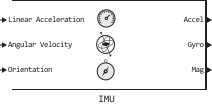
Block IMU simulates data acquisition from an Inertial Measurement Unit (IMU) consisting of an accelerometer, gyroscope, and magnetometer. Using the parameter Reference frame you can specify the coordinate system for the block input signals in the format NED (north-east-down) or ENU (east-north-up).
Ports
Input
#
Linear Acceleration
—
acceleration of the inertial measuring unit in the local navigation coordinate system, m/s2
the matrix
Details
Acceleration of the inertial measuring unit in the local navigation coordinate system, defined as a matrix of real scalars in m/s2 size on , where — the number of counts in the current frame. Do not include gravity acceleration in this port, as the sensor simulates it by default.
To set the orientation of the coordinate system of the sensor housing of the inertial measurement unit relative to the local navigation coordinate system, use the Orientation input port.
| Data types |
|
| Complex numbers support |
No |
#
Angular Velocity
—
angular velocity of the inertial measuring unit in the local navigation coordinate system, rad/s
the matrix
Details
The angular velocity of the coordinate system of the sensor housing of the inertial measuring unit in the local navigation coordinate system, defined as a matrix of real scalars in rad/s size on , where — the number of counts in the current frame.
To set the orientation of the coordinate system of the sensor housing of the inertial measurement unit relative to the local navigation coordinate system, use the Orientation input port.
| Data types |
|
| Complex numbers support |
No |
#
Orientation
—
orientation of the inertial measuring unit in the local navigation coordinate system
array | the matrix
Details
The orientation of the coordinate system of the sensor housing of the inertial measuring unit relative to the local navigation coordinate system, defined as an array of real scalars of the size on or as a rotation matrix of size on on , where — the number of counts in the current frame. Each row of the array on It counts as four elements of the function quaternion.
| Data types |
|
| Complex numbers support |
No |
#
Temperature
—
temperature of the inertial measuring unit, °C
vector
Details
The temperature of the inertial measuring unit, set as a vector of size on real scalars in degrees Celsius.
Dependencies
To use this port, check the box Specify temperature from input port.
| Data types |
|
| Complex numbers support |
No |
#
Magnetic Field
—
magnetic field vector in the local navigation coordinate system, MCT
the matrix
Details
The vector of the magnetic field in the local navigation coordinate system, defined as a matrix of the size on real scalars in mkTl.
Dependencies
To use this port, check the box Specify magnetic field from input port.
| Data types |
|
| Complex numbers support |
No |
Output
#
Accel
—
measurement of the accelerometer of the inertial measuring unit in the coordinate system of the sensor housing, m/s2
the matrix
Details
Measurement of the accelerometer of the inertial measuring unit in the coordinate system of the sensor housing, returned as a matrix of real scalars in m/s2 size on , where — the number of counts in the current frame.
| Data types |
|
| Complex numbers support |
No |
#
Gyro
—
measurement of the gyroscope of the inertial measuring unit in the coordinate system of the sensor housing, rad/s
the matrix
Details
Measurement of the gyroscope of the inertial measuring unit in the coordinate system of the sensor housing, returned as a matrix of real scalars in rad/s size on , where — the number of counts in the current frame.
| Data types |
|
| Complex numbers support |
No |
#
Mag
—
measurement of the magnetometer of the inertial measuring unit in the coordinate system of the sensor housing, MCT
the matrix
Details
Measurement of the magnetometer of the inertial measuring unit in the coordinate system of the sensor housing, returned as a matrix of real scalars in MCT size on , where — the number of counts in the current frame.
| Data types |
|
| Complex numbers support |
No |
Parameters
Gyroscope
Main
# Constant offset bias (m/s²) — constant sensor displacement, m/s2
Details
The constant displacement of the sensor in m/s 2, specified as a real scalar or a three-element vector string. Any scalar input signal is converted into a real three-element vector string, where each element has the value of the input scalar.
| Default value |
|
| Program usage name |
|
| Tunable |
Yes |
| Evaluatable |
Yes |
# Axes skew (%) — misalignment of sensor axes, %
Details
The skew of the sensor axes in percentages, specified as a scalar, a three-element row vector or a matrix of size on . The diagonal elements of the matrix take into account the effects of displacement for each axis, and the non-diagonal elements take into account the effects of displacement between the axes. Measured state it is obtained from the true state through the displacement matrix as follows:
-
If you set the parameter as a scalar, all non-diagonal elements of the matrix take the value of the specified scalar, and all diagonal elements are equal
100. -
If you set the parameter as a vector , then , and . All diagonal elements are equal
100.
| Default value |
|
| Program usage name |
|
| Tunable |
Yes |
| Evaluatable |
Yes |
#
Maximum readings (rad/s) —
maximum sensor reading, rad/s
Real number
Details
The maximum sensor reading in rad/s, set as a positive real scalar.
| Default value |
|
| Program usage name |
|
| Tunable |
Yes |
| Evaluatable |
Yes |
#
Resolution (rad/s) —
sensor measurement resolution, rad/s
Real number
Details
The measurement resolution of the sensor in rad/s, set as a non-negative real scalar.
| Default value |
|
| Program usage name |
|
| Tunable |
Yes |
| Evaluatable |
Yes |
# Bias from acceleration ((rad/s)/(m/s²)) — sensor displacement caused by linear acceleration, (rad/s)/(m/s2)
Details
Sensor displacement caused by linear acceleration, in (rad/s)/(m/s2), given as a real scalar or a three-element string vector. Any scalar input signal is converted into a real three-element vector string, where each element has the value of the input scalar.
| Default value |
|
| Program usage name |
|
| Tunable |
Yes |
| Evaluatable |
Yes |
Noise
# Bias instability filter numerator coefficients — coefficients of the numerator of the bias instability filter
Details
Coefficients of the numerator of the bias instability filter, specified as a vector string of real values.
| Default value |
|
| Program usage name |
|
| Tunable |
Yes |
| Evaluatable |
Yes |
# Bias instability filter denominator coefficients — denominator coefficients of the bias instability filter
Details
Coefficients of the denominator of the bias instability filter, specified as a vector string of real values.
| Default value |
|
| Program usage name |
|
| Tunable |
Yes |
| Evaluatable |
Yes |
#
Noise type —
type of random noise
double-sided | single-sided
Details
Select the type of random noise:
-
double-sided— random noise coefficients have a scale factor2; -
single-sided— random noise coefficients have a scale factor1.
| Values |
|
| Default value |
|
| Program usage name |
|
| Tunable |
No |
| Evaluatable |
No |
# Angle random walk ((rad/s)/√Hz) — random angular walk, (rad/s)/√Hz
Details
The random angular walk of the sensor in (rad/s)/√Hz, specified as a real scalar or a three-element vector string. Any scalar input signal is converted into a real three-element vector string, where each element has the value of the input scalar.
| Default value |
|
| Program usage name |
|
| Tunable |
Yes |
| Evaluatable |
Yes |
# Bias instability (rad/s) — displacement instability, rad/s
Details
The instability of the displacement in rad/s, specified as a real scalar or a three-element vector string. Any scalar input signal is converted into a real three-element vector string, where each element has the value of the input scalar.
| Default value |
|
| Program usage name |
|
| Tunable |
Yes |
| Evaluatable |
Yes |
# Rate random walk ((rad/s)*√Hz) — integrated white noise sensor, (rad/s)√Hz
Details
Integrated white noise of the sensor in (rad/s)√Hz, specified as a real scalar or a three-element vector string. Any scalar input signal is converted into a real three-element vector string, where each element has the value of the input scalar.
| Default value |
|
| Program usage name |
|
| Tunable |
Yes |
| Evaluatable |
Yes |
Temperature Effects
# Temperature scale factor (%/°C) — error of the scale factor relative to temperature, %/°C
Details
The error of the scale factor relative to temperature in %/°C, specified as a real scalar or a real three-element vector, is a string with values ranging from 0 before 100. Any scalar input signal is converted into a real three-element vector string, where each element has the value of the input scalar.
| Default value |
|
| Program usage name |
|
| Tunable |
Yes |
| Evaluatable |
Yes |
# Bias from temperature ((rad/s)/°C) — sensor displacement caused by temperature, (rad/s)/°C
Details
The displacement of the sensor caused by temperature, in (rad/s)/°C, specified as a real scalar or a three-element vector string. Any scalar input signal is converted into a real three-element vector string, where each element has the value of the input scalar.
| Default value |
|
| Program usage name |
|
| Tunable |
Yes |
| Evaluatable |
Yes |
Magnetometer
Main
# Axes skew (%) — misalignment of sensor axes, %
Details
The skew of the sensor axes in percentages, specified as a scalar, a three-element row vector or a matrix of size on . The diagonal elements of the matrix take into account the effects of displacement for each axis, and the non-diagonal elements take into account the effects of displacement between the axes. Measured state it is obtained from the true state through the displacement matrix as follows:
-
If you set the parameter as a scalar, all non-diagonal elements of the matrix take the value of the specified scalar, and all diagonal elements are equal
100. -
If you set the parameter as a vector , then , and . All diagonal elements are equal
100.
| Default value |
|
| Program usage name |
|
| Tunable |
Yes |
| Evaluatable |
Yes |
#
Maximum readings (µT) —
maximum sensor reading, MCT
Real number
Details
The maximum sensor reading in MCT, set as a positive real scalar.
| Default value |
|
| Program usage name |
|
| Tunable |
Yes |
| Evaluatable |
Yes |
#
Resolution ((µT)/LSB) —
sensor measurement resolution, mcTl/NZB
Real number
Details
The resolution of the sensor measurements in mcTl/NCB, set as a non-negative real scalar.
| Default value |
|
| Program usage name |
|
| Tunable |
Yes |
| Evaluatable |
Yes |
# Constant offset bias (µT) — constant displacement of the sensor, MCT
Details
The constant displacement of the sensor in the MCT, specified as a real scalar or a three-element vector string. Any scalar input signal is converted into a real three-element vector string, where each element has the value of the input scalar.
| Default value |
|
| Program usage name |
|
| Tunable |
Yes |
| Evaluatable |
Yes |
Noise
# Bias instability filter numerator coefficients — coefficients of the numerator of the bias instability filter
Details
Coefficients of the numerator of the bias instability filter, specified as a vector string of real values.
| Default value |
|
| Program usage name |
|
| Tunable |
Yes |
| Evaluatable |
Yes |
# Bias instability filter denominator coefficients — denominator coefficients of the bias instability filter
Details
Coefficients of the denominator of the bias instability filter, specified as a vector string of real values.
| Default value |
|
| Program usage name |
|
| Tunable |
Yes |
| Evaluatable |
Yes |
#
Noise type —
type of random noise
double-sided | single-sided
Details
Select the type of random noise:
-
double-sided— random noise coefficients have a scale factor2; -
single-sided— random noise coefficients have a scale factor1.
| Values |
|
| Default value |
|
| Program usage name |
|
| Tunable |
No |
| Evaluatable |
No |
# White Noise PSD ((µT)/√Hz) — spectral noise power density of the sensor, ΜTL/√Hz
Details
The spectral power density of the sensor noise in ΜTL/√Hz, specified as a real scalar or a three-element vector string. Any scalar input signal is converted into a real three-element vector string, where each element has the value of the input scalar.
| Default value |
|
| Program usage name |
|
| Tunable |
Yes |
| Evaluatable |
Yes |
# Bias instability (µT) — displacement instability, MCT
Details
The instability of the displacement in the mcTl, defined as a real scalar or a three-element vector string. Any scalar input signal is converted into a real three-element vector string, where each element has the value of the input scalar.
| Default value |
|
| Program usage name |
|
| Tunable |
Yes |
| Evaluatable |
Yes |
# Random walk ((µT)*√Hz) — Integrated white noise sensor, mcTl⋅√Hz
Details
Integrated white noise of the sensor in mcTl⋅√Hz, specified as a real scalar or a three-element vector string. Any scalar input signal is converted into a real three-element vector string, where each element has the value of the input scalar.
| Default value |
|
| Program usage name |
|
| Tunable |
Yes |
| Evaluatable |
Yes |
Temperature Effects
# Temperature scale factor (%/°C) — error of the scale factor relative to temperature, %/°C
Details
The error of the scale factor relative to temperature in %/°C, specified as a real scalar or a real three-element vector, is a string with values ranging from 0 before 100. Any scalar input signal is converted into a real three-element vector string, where each element has the value of the input scalar.
| Default value |
|
| Program usage name |
|
| Tunable |
Yes |
| Evaluatable |
Yes |
# Bias from temperature ((µT)/°C) — sensor displacement caused by temperature, MCT/°C
Details
The displacement of the sensor caused by temperature, in µT/°C, specified as a real scalar or a three-element vector string. Any scalar input signal is converted into a real three-element vector string, where each element has the value of the input scalar.
| Default value |
|
| Program usage name |
|
| Tunable |
Yes |
| Evaluatable |
Yes |
Parameters
Main
#
Reference frame —
navigation coordinate system
ENU | NED
Details
The navigation coordinate system, set as NED (north-east-down) or ENU (east-north-up).
|
| Values |
|
| Default value |
|
| Program usage name |
|
| Tunable |
No |
| Evaluatable |
No |
Environment
#
Specify temperature from input port —
the ability to set the temperature through the input port
Logical
Details
Select this option to set the temperature via the Temperature input port.
| Default value |
|
| Program usage name |
|
| Tunable |
No |
| Evaluatable |
No |
#
Temperature (°C) —
operating temperature of the inertial measuring unit, °C
Real number
Details
The operating temperature of the inertial measuring unit in degrees Celsius, set as a real scalar.
When calculating temperature scale factors and ambient drift noise, the nominal temperature is used 25 °C.
Dependencies
To use this option, uncheck the box. Specify temperature from input port.
| Default value |
|
| Program usage name |
|
| Tunable |
Yes |
| Evaluatable |
Yes |
#
Specify magnetic field from input port —
the ability to set the magnetic field through the input port
Logical
Details
Select this option to set the magnetic field via the Magnetic Field input port.
| Default value |
|
| Program usage name |
|
| Tunable |
No |
| Evaluatable |
No |
#
Magnetic field (NED) —
the vector of the magnetic field in the coordinate system NED, mkTl
Vector / matrix of real numbers
Details
The vector of the magnetic field, expressed in the navigation coordinate system NED, defined as a vector of scalars of size on .
The default magnetic field corresponds to the magnetic field at zero latitude, zero longitude, and zero altitude.
Dependencies
To use this parameter, set for the parameter Reference frame meaning NED and uncheck the box Specify magnetic field from input port.
| Default value |
|
| Program usage name |
|
| Tunable |
Yes |
| Evaluatable |
Yes |
#
Magnetic field (ENU) —
the vector of the magnetic field in the coordinate system ENU, mkTl
Vector / matrix of real numbers
Details
The vector of the magnetic field, expressed in the navigation coordinate system ENU, defined as a vector of scalars of size on .
The default magnetic field corresponds to the magnetic field at zero latitude, zero longitude, and zero altitude.
Dependencies
To use this parameter, set for the parameter Reference frame meaning ENU and uncheck the box Specify magnetic field from input port.
| Default value |
|
| Program usage name |
|
| Tunable |
Yes |
| Evaluatable |
Yes |
Randomization
#
Seed —
initial value for randomization
Real number
Details
The initial value of the random number generator, set as a non-negative integer.
| Default value |
|
| Program usage name |
|
| Tunable |
No |
| Evaluatable |
Yes |
Accelerometer
Main
#
Maximum readings (m/s²) —
maximum sensor reading, m/s2
Real number
Details
The maximum sensor reading in m/s is 2, set as a positive real scalar.
| Default value |
|
| Program usage name |
|
| Tunable |
Yes |
| Evaluatable |
Yes |
#
Resolution ((m/s²)/LSB) —
sensor measurement resolution, (m/s2)/NSB
Real number
Details
Sensor measurement resolution in (m/s2)/NSB (Least Significant Bit), set as a non-negative real scalar.
| Default value |
|
| Program usage name |
|
| Tunable |
Yes |
| Evaluatable |
Yes |
# Constant offset bias (m/s²) — constant sensor displacement, m/s2
Details
The constant displacement of the sensor in m/s 2, specified as a real scalar or a three-element vector string. Any scalar input signal is converted into a real three-element vector string, where each element has the value of the input scalar.
| Default value |
|
| Program usage name |
|
| Tunable |
Yes |
| Evaluatable |
Yes |
# Axes skew (%) — misalignment of sensor axes, %
Details
The skew of the sensor axes in percentages, specified as a scalar, a three-element row vector or a matrix of size on . The diagonal elements of the matrix take into account the effects of displacement for each axis, and the non-diagonal elements take into account the effects of displacement between the axes. Measured state it is obtained from the true state through the displacement matrix as follows:
-
If you set the parameter as a scalar, all non-diagonal elements of the matrix take the value of the specified scalar, and all diagonal elements are equal
100. -
If you set the parameter as a vector , then , and . All diagonal elements are equal
100.
| Default value |
|
| Program usage name |
|
| Tunable |
Yes |
| Evaluatable |
Yes |
Noise
# Velocity random walk ((m/s²)/√Hz) — random walk, (m/s2)/√Hz
Details
A random walk in (m/s2)/√Hz, given as a real scalar or a three-element string vector. This parameter corresponds to the spectral power density of the sensor noise. Any scalar input signal is converted into a real three-element vector string, where each element has the value of the input scalar.
| Default value |
|
| Program usage name |
|
| Tunable |
Yes |
| Evaluatable |
Yes |
# Bias instability (m/s²) — displacement instability, m/s2
Details
The instability of the displacement in m/s 2, given as a real scalar or a three-element vector string. Any scalar input signal is converted into a real three-element vector string, where each element has the value of the input scalar.
| Default value |
|
| Program usage name |
|
| Tunable |
Yes |
| Evaluatable |
Yes |
# Bias instability filter numerator coefficients — coefficients of the numerator of the bias instability filter
Details
Coefficients of the numerator of the bias instability filter, specified as a vector string of real values.
| Default value |
|
| Program usage name |
|
| Tunable |
Yes |
| Evaluatable |
Yes |
# Bias instability filter denominator coefficients — denominator coefficients of the bias instability filter
Details
Coefficients of the denominator of the bias instability filter, specified as a vector string of real values.
| Default value |
|
| Program usage name |
|
| Tunable |
Yes |
| Evaluatable |
Yes |
# Acceleration random walk ((m/s²)*√Hz) — random walk acceleration, (m/s2)√Hz
Details
The random walk of the sensor acceleration in (m/s2)√Hz, given as a real scalar or a three-element string vector. Any scalar input signal is converted into a real three-element vector string, where each element has the value of the input scalar.
| Default value |
|
| Program usage name |
|
| Tunable |
Yes |
| Evaluatable |
Yes |
#
Noise type —
type of random noise
double-sided | single-sided
Details
Select the type of random noise:
-
double-sided— random noise coefficients have a scale factor2; -
single-sided— random noise coefficients have a scale factor1.
| Values |
|
| Default value |
|
| Program usage name |
|
| Tunable |
No |
| Evaluatable |
No |
Temperature Effects
# Bias from temperature ((m/s²)/°C) — sensor displacement caused by temperature, (m/s2)/°C
Details
The displacement of the sensor caused by temperature, in (m/s2)/°C, specified as a real scalar or a three-element vector string. Any scalar input signal is converted into a real three-element vector string, where each element has the value of the input scalar.
| Default value |
|
| Program usage name |
|
| Tunable |
Yes |
| Evaluatable |
Yes |
# Temperature scale factor (%/°C) — error of the scale factor relative to temperature, %/°C
Details
The error of the scale factor relative to temperature in %/°C, specified as a real scalar or a real three-element vector, is a string with values ranging from 0 before 100. Any scalar input signal is converted into a real three-element vector string, where each element has the value of the input scalar.
| Default value |
|
| Program usage name |
|
| Tunable |
Yes |
| Evaluatable |
Yes |
Algorithms
Accelerometer
Details
The description of the algorithm below assumes the use of a navigation coordinate system. NED. The accelerometer model uses orientation and acceleration inputs derived from reference values.,
to simulate accelerometer readings.

_ Getting full acceleration_
To get full acceleration boost it is preprocessed by inverting and adding the vector of the gravitational constant ( m/s2 in the coordinate system NED):
Acceleration is inverted to produce zero readings of total acceleration when the accelerometer is in free fall. Boost it is also called specific force.
conversion to the sensor coordinate system
The total acceleration is converted from the local navigation coordinate system to the sensor coordinate system using the following formula:
where — orientation. If it is set as a quaternion, it is converted to a rotation matrix before processing.
The main model
The reference acceleration set in the sensor coordinate system, runs through the main model, which adds misalignment and misalignment:
where — parameter value Constant offset bias (m/s²), and , and — parameter elements Axes skew (%).
The displacement instability rate_
Drift of displacement instability It is modeled as offset white noise with subsequent filtering.:
where
-
— the index of the discrete time step; the size of the discrete time step is the inverse of the sampling frequency ;
-
— parameter value Bias instability (m/s²);
-
— white noise obeying a normal distribution with an average value
0and the variance1; -
— the coefficients of the denominator specified in the parameter Bias instability filter denominator coefficients;
-
— numerator coefficients specified in the parameter Bias instability filter numerator coefficients;
-
and — the orders of the coefficients of the denominator and numerator, respectively.
The white noise drift
The white noise drift is modeled by multiplying the elements of a random white noise stream by the standard deviation:
where
-
— white noise obeying a normal distribution with an average value
0and the variance1; -
— sampling rate;
-
— the noise density specified in the parameter Velocity random walk ((m/s²)/√Hz);
-
— a scale variable equal to
2if for the parameter Noise type the value is setdouble-sided, and1if for the parameter Noise type the value is setsingle-sided.
The random walk rate
The drift of a random walk is modeled by shifting elements of a random white noise stream and subsequent filtering.:
where
-
— the index of the discrete time step; the size of the discrete time step is the inverse of the value ;
-
— the random walk specified in the parameter Acceleration random walk ((m/s²)*√Hz);
-
— sampling rate;
-
— white noise obeying a normal distribution with an average value
0and the variance1; -
— a scale variable equal to
2if for the parameter Noise type the value is setdouble-sided, and1if for the parameter Noise type the value is setsingle-sided.
The noise of environmental drift
Ambient drift noise is modeled by multiplying the temperature difference relative to the standard by the temperature offset.:
where — the temperature set in the parameter Temperature (°C), and — parameter value Bias from temperature ((m/s²)/°C). The standard temperature is 25 °C.
The scale factor error model_
The error of the temperature scale factor is modeled as follows:
where — the temperature set in the parameter Temperature (°C), and — parameter value Temperature scale factor (%/°C). The standard temperature is 25 °C.
The quantization model_
Quantization is modeled by pre-saturating the continuous signal model:
and then setting permissions:
where
-
— accelerometer readings;
-
— the measurement range specified in the parameter Maximum readings (m/s²);
-
— parameter value Resolution ((m/s²)/LSB).
Gyroscope
Details
The description of the algorithm below assumes the use of a navigation coordinate system. NED. The gyroscope model uses orientation, acceleration, and angular velocity inputs derived from reference values.,
to simulate gyroscope readings.

conversion to the sensor coordinate system
Angular velocity It is converted from the local navigation coordinate system to the sensor coordinate system using the following formula:
where — reference orientation. If it is set as a quaternion, it is converted to a rotation matrix before processing.
The main model
The reference angular velocity set in the sensor coordinate system, goes through the main model, which adds misalignment and misalignment:
where — parameter value Constant offset bias (m/s²), and , and — parameter elements Axes skew (%).
The displacement instability rate_
Drift of displacement instability It is modeled as offset white noise with subsequent filtering.:
where
-
— the index of the discrete time step; the size of the discrete time step is the inverse of the sampling frequency ;
-
— parameter value Bias instability (rad/s);
-
— white noise obeying a normal distribution with an average value
0and the variance1; -
— the coefficients of the denominator specified in the parameter Bias instability filter denominator coefficients;
-
— numerator coefficients specified in the parameter Bias instability filter numerator coefficients;
-
and — the orders of the coefficients of the denominator and numerator, respectively.
The white noise drift
The white noise drift is modeled by multiplying the elements of a random white noise stream by the standard deviation:
where
-
— white noise obeying a normal distribution with an average value
0and the variance1; -
— sampling rate;
-
— the noise density specified in the parameter Angle random walk ((rad/s)/√Hz);
-
— a scale variable equal to
2if for the parameter Noise type the value is setdouble-sided, and1if for the parameter Noise type the value is setsingle-sided.
The random walk rate
The drift of a random walk is modeled by shifting elements of a random white noise stream and subsequent filtering.:
where
-
— the index of the discrete time step; the size of the discrete time step is the inverse of the value ;
-
— the random walk specified in the parameter Rate random walk ((rad/s)*√Hz);
-
— sampling rate;
-
— white noise obeying a normal distribution with an average value
0and the variance1; -
— a scale variable equal to
2if for the parameter Noise type the value is setdouble-sided, and1if for the parameter Noise type the value is setsingle-sided.
The noise of environmental drift
Ambient drift noise is modeled by multiplying the temperature difference relative to the standard by the temperature offset.:
where — the temperature set in the parameter Temperature (°C), and — parameter value Bias from temperature ((rad/s)/°C). The standard temperature is 25 °C.
Acceleration offset drift_
The acceleration offset drift is modeled by multiplying the acceleration input signal by the acceleration offset:
where — acceleration, eh — parameter value Bias from acceleration rad/s)/(m/s².
The scale factor error model_
The error of the temperature scale factor is modeled as follows:
where — the temperature set in the parameter Temperature (°C), and — parameter value Temperature scale factor (%/°C). The standard temperature is 25 °C.
The quantization model_
Quantization is modeled by pre-saturating the continuous signal model:
and then setting permissions:
where
-
— gyroscope readings;
-
— the measurement range specified in the parameter Maximum readings (rad/s);
-
— parameter value Resolution (rad/s).
Magnetometer
Details
The description of the algorithm below assumes the use of a navigation coordinate system. NED. The magnetometer model uses orientation, acceleration, and angular velocity inputs derived from reference values.,
to simulate magnetometer readings.

conversion to the sensor coordinate system
Full acceleration It is converted from the local navigation coordinate system to the sensor coordinate system using the following formula:
where — reference orientation. If it is set as a quaternion, it is converted to a rotation matrix before processing.
The main model
The reference acceleration set in the sensor coordinate system, goes through the main model, which adds misalignment and misalignment:
where — parameter value Constant offset bias (µT), and , and — parameter elements Axes skew (%).
The displacement instability rate_
Drift of displacement instability It is modeled as offset white noise with subsequent filtering.:
where
-
— the index of the discrete time step; the size of the discrete time step is the inverse of the sampling frequency ;
-
— parameter value Bias instability (µT);
-
— white noise obeying a normal distribution with an average value
0and the variance1; -
— the coefficients of the denominator specified in the parameter Bias instability filter denominator coefficients;
-
— numerator coefficients specified in the parameter Bias instability filter numerator coefficients;
-
and — the orders of the coefficients of the denominator and numerator, respectively.
The white noise drift
The white noise drift is modeled by multiplying the elements of a random white noise stream by the standard deviation:
where
-
— white noise obeying a normal distribution with an average value
0and the variance1; -
— sampling rate;
-
— the noise density specified in the parameter White Noise PSD ((µT)/√Hz);
-
— a scale variable equal to
2if for the parameter Noise type the value is setdouble-sided, and1if for the parameter Noise type the value is setsingle-sided.
The random walk rate
The drift of a random walk is modeled by shifting elements of a random white noise stream and subsequent filtering.:
where
-
— the index of the discrete time step; the size of the discrete time step is the inverse of the value ;
-
— the random walk specified in the parameter Random walk ((µT)*√Hz);
-
— sampling rate;
-
— white noise obeying a normal distribution with an average value
0and the variance1; -
— a scale variable equal to
2if for the parameter Noise type the value is setdouble-sided, and1if for the parameter Noise type the value is setsingle-sided.
The noise of environmental drift
Ambient drift noise is modeled by multiplying the temperature difference relative to the standard by the temperature offset.:
where — the temperature set in the parameter Temperature (°C), and — parameter value Bias from temperature ((µT)/°C). The standard temperature is 25 °C.
The scale factor error model_
The error of the temperature scale factor is modeled as follows:
where — the temperature set in the parameter Temperature (°C), and — parameter value Temperature scale factor (%/°C). The standard temperature is 25 °C.
The quantization model_
Quantization is modeled by pre-saturating the continuous signal model:
and then setting permissions:
where
-
— magnetometer readings;
-
— the measurement range specified in the parameter Maximum readings (µT);
-
— parameter value Resolution ((µT)/LSB).