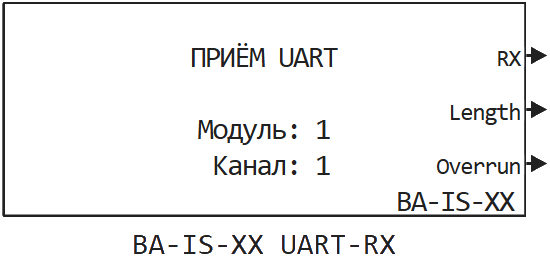
BA-IS-XX UART-RX
Receiving data via UART with the usage of the RITMeX BA-IS-XX I/O module.
blockType: CFunction
|
Path in the library: |
Description
| To work with the block, install/update the support package RITM blocks. |
Block BA-IS-XX UART-RX It is used to receive data via UART with the usage of the RITMeX BA-IS-XX I/O module.
Ports
Output
#
RX
—
array received via UART
vector
Details
The size of the array is fixed and is 16 (see section for details Remarks about usage)
| Data types |
|
| Complex numbers support |
No |
#
Length
—
information on the number of bytes received via UART per calculation step
scalar
Details
| Data types |
|
| Complex numbers support |
No |
#
Overrun
—
a non-zero value on this output means that external data is coming in faster than the block is reading it.
scalar
Details
| Data types |
|
| Complex numbers support |
No |
Parameters
Main group
#
Номер модуля: —
unique identification of the module
1 | 3 | 4 | 5 | 6 | 7 | 8
Details
It is used to uniquely identify a module when more than one I/O module of the same type is installed in a real-time machine.
The module numbers are signed on the case of the KPM "RITM".
| Values |
|
| Default value |
|
| Program usage name |
|
| Tunable |
No |
| Evaluatable |
Yes |
#
Номер канала: —
UART channel for reception
1 | 2 | 3 | 4 | 5 | 6 | 7 | 8 | 9 | 10 | 11 | 12 | 13 | 14 | 15 | 16 | 17 | 18 | 19 | 20 | 21 | 22 | 23 | 24 | 25 | 26 | 27 | 28 | 29 | 30 | 31 | 32
Details
| Values |
|
| Default value |
|
| Program usage name |
|
| Tunable |
No |
| Evaluatable |
Yes |
# Макс. количество слов: — the number of words read from the UART buffer per calculation step
Details
| Default value |
|
| Program usage name |
|
| Tunable |
No |
| Evaluatable |
Yes |
# Шаг расчёта, с: — the calculation step by which the UART data is received into the real-time application
Details
| Default value |
|
| Program usage name |
|
| Tunable |
No |
| Evaluatable |
Yes |
Remarks about usage
_ Detailed notes on usage_
The UART module on the FPGA contains two hardware buffers: for receiving and sending. The size of each buffer — 16 bytes. In this regard, it is necessary to have a good understanding of the characteristics of a particular UART communication protocol in order to avoid overflowing these buffers, as well as to ensure that the previous message is sent before trying to send the next one.
The first thing to consider is the data transfer rate. Obviously, UART data is not transmitted instantly. Suppose, for example, you want to send an array from 16 characters (each character consists of 10 the bit is 8 data bit, start and stop bits) with speed 115200 bode. This will require seconds. If the Sending UART block works in increments 0.001 c, then the data will not have time to go to the next step of the block calculation, because 0.001 < 0.0014. Therefore, the next array of characters cannot be sent and in such a situation the execution of the model will be stopped with an error. It is required to select such a combination of the block calculation step, the transfer rate and the size of the array so that it is physically possible to send this data in one block calculation step.
*The second thing to consider is the size of the hardware receive buffer. If the data from the outside comes faster than the block BA-IS-XX UART-TX reads them from the hardware buffer, then new data that does not fit into the receive buffer is discarded. Thus, it is necessary to take into account and calculate the expected time to fill the read buffer with an external data stream.
To do this, you can use the values on the Length and Overrun outputs of the BA-IS-XX UART-TX block. In calculations within the model, exactly as many elements should be taken into account at the output of the RX block as were actually received (output Length). The values of all other elements of the RX array are not defined.
If a non-zero value is output at the output of the Overrun block, it means that the hardware buffer has overflowed and the data in the hardware receive buffer has been lost. In this case, it is possible to reduce the calculation step of the BA-IS-XX UART-TX block in order to read data more often and thus avoid overflowing the receive buffer. The calculation step is too small for the BA-IS-XX UART-TX block, it should also not be set, but should be guided by a specific exchange protocol. For example, if it is known that an external device sends commands of 8 bytes, you can choose such a block calculation step so that the Length output value is approximately equal to 8 from step to step calculation.