EngeeComms.OFDMDemodulatorBaseband
Demodulation using the OFDM method.
| Library |
|
| Block |
Description
The system object EngeeComms.OFDMDemodulatorBaseband demodulates the input signal using the orthogonal frequency division multiplexed channel division multiplexing (OFDM) method in the time domain and outputs subcarriers based on OFDM parameters.
For more information, see OFDM Modulator. The output is a broadband representation of the input signal for the system object EngeeComms.OFDMModulatorBaseband.
To demodulate an OFDM signal, follow the steps below:
-
Create an
EngeeComms.OFDMDemodulatorBasebandobject and set its properties. -
Call the object with arguments as if it were a function. To learn more about how system objects work, see Engee System Objects.
Syntax
Creation
-
ofdmDemod = EngeeComms.OFDMDemodulatorBasband()creates an OFDM demodulator that demodulates the input signal using the frequency-division orthogonal demodulation method, with by default property values.Example:
ofdmDemod = EngeeComms.OFDMDemodulatorBaseband() -
ofdmDemod = EngeeComms.OFDMDemodulatorBaseband(Name=Value)creates an OFDM demodulator with each specified property Name (name) set to the specified Value (value). You can specify additional arguments as a name-value pair in any order (Name1=Value1,…,NameN=ValueN).Example:
ofdmDemod = EngeeComms.OFDMDemodulatorBaseband(FFTLength=64)
Usage
-
Y = ofdmDemod(X)demodulates the time domain input signal using the OFDM method and returns the demodulated OFDM baseband signal. -
[Y,pilot] = ofdmDemod(X)splits the pilot signal into the subcarriers specified in the value of the PilotCarrierIndices property. To use this syntax, set the PilotOutputPort property totrue.
Arguments
Input arguments
X -
OFDM modulated wideband input signal
matrix
Details
OFDM modulated wideband signal specified as a matrix
-
- oversampling factor defined by the OversamplingFactor property.
-
-
- length of cyclic prefix over all symbols.
-
- the length of the cyclic prefix defined by the CyclicPrefixLength property.
-
If CyclicPrefixLength is a scalar, .
-
If CyclicPrefixLength is a vector of strings, .
-
-
- The number of subcarriers defined by the FFTLength parameters.
-
- number of symbols, defined by the NumberOfOFDMSymbols parameters.
-
- number of receiving antennas defined by the NumberOfReceiveAntennas parameters.
| Data types |
|
| Support for complex numbers |
Yes |
Output arguments
Y -
demodulated output signal
matrix | 3D array
Details
Demodulated output signal returned as a matrix or array
at to of the same data type as the input signal. The output signal is reduced to a matrix if is 1.
-
- number of data subcarriers.
-
- the number of symbols defined by the NumSymbols. property.
-
- number of receiving antennas, defined by the NumReceiveAntennnas property.
| Data types |
|
| Support for complex numbers |
Yes |
pilot -
pilot signal
3D array | 4D array
Details
A pilot signal returned with the same data type as the input signal. Defined as:
-
3D array of size to to , when the PilotCarrierIndices property is a vector or matrix.
-
4D array of size to to to , when the PilotCarrierIndices property is a 3D array.
Where:
* - the number of pilot subcarriers in each symbol, defined by size(PilotCarrierIndices,1).
* - the number of symbols defined by the NumSymbols property.
* - the number of receiving antennas, defined by the NumReceiveAntennnas property.
* - number of transmit antennas.
Dependencies
To use this argument, set the PilotOutputPort property to true.
Properties
FFTLength -
number of FFT points
64 (by default) | `positive integer `
Details
The number of Fast Fourier Transform (FFT) points specified as a positive integer scalar. The length of the FFT must be and equivalent to the number of subcarriers.
NumGuardBandCarriers -.
number of subcarriers allocated to the left and right guard bands
[6; 5] (by default) | Enumeric vector 2 by 1
Details
The number of subcarriers allocated to the left and right guard bands, given as a 2-by-1 integer vector.
The number of subcarriers of the left and right guard bands, , shall be within , where is the total number of subcarriers in the OFDM signal as determined by the FFTLength property.
RemoveDCCarrier -
exclude or include the zero frequency subcarrier
false or 0 (by default) | true or 1
Details
Option to remove the DC zero subcarrier, specified as numeric or logical 0 (false) or 1 (true). The zero frequency subcarrier is located in the centre of the frequency band and has an index value:
-
, if the value of is even.
-
, if the value of is odd.
- is the total number of subcarriers in the OFDM signal defined by the FFTLength property.
PilotOutputPort — pilot subcarrier output
false or 0 (by default) | true or 1
Details
Pilot subcarrier output option specified as numeric or logical 0 (false) or 1 (true).
-
0(false) - pilot information may be present but remains embedded in the output. -
1(true) - the block separates the subcarriers specified by the PilotSubcarrierIndices property from the output data and outputs the demodulated pilot signal in the pilot argument.
PilotCarrierIndices — pilot subcarrier location indices
[12; 26; 40; 54] (by default) | column vector | matrix | 3D array
Details
Pilot subcarrier location indices specified as a column vector, matrix or 3D array with integer element values in the range of
,
where
-
- is the total number of subcarriers in the OFDM signal, defined by the FFTLength property.
-
and are the left and right guard bands defined by the NumberOfGuardBands property value.
The pilot carrier indices can be assigned the same or different subcarriers for each symbol and for all transmitting antennas .
-
If the pilot indices are the same for each symbol and transmitting antenna, the parameters have the dimension by 1.
-
If the pilot indices are different for each symbol, the parameters have the dimension by .
-
If the received signal is assigned one symbol on several transmitting antennas, the parameters has the dimension by 1 to .
-
If the indices differ in the number of symbols and transmitting antennas, the parameters have the dimension to to .
| To minimise interference between transmissions to more than one transmitting antenna, the pilot indices per symbol should be mutually different for all antennas. |
Dependencies
To use this property, set the PilotOutputPort property to 1.
CyclicPrefixLength -.
cyclic prefix length
16 (by default) | positive integer | vector-string | vector-string
Details
The length of the cyclic prefix for each OFDM character, specified as a positive integer scalar or string vector containing the number of OFDM character elements. When specifying the length of the cyclic prefix as:
-
Scalar- the length of the cyclic prefix is the same for all symbols through all antennas. -
Vector-string- the length of the cyclic prefix can vary between symbols, but does not vary between antennas.
OversamplingFactor -
oversampling factor
1 (by default) | positive integer
Details
The oversampling factor specified as a positive scalar. The oversampling factor must satisfy these constraints:
-
The product of OversamplingFactor by FFTLength must be an integer.
-
The product of OversamplingFactor over CyclicPrefixLength must be an integer.
If OversamplingFactor is specified as an irrational number, specify a fractional value. For example, given FFTLength 12 and OversamplingFactor 4/3, their product is the integer 16. However, rounding 4/3 to 1,333 when OversamplingFactor is set results in a non-integer product of 15,9960, which causes an error.
|
| Data types |
|
NumSymbols -
number of OFDM characters
1 (by default) | positive integer
Details
The number of OFDM characters in the time-frequency grid, specified as a positive integer scalar.
NumReceiveAntennnas -
number of receiving antennas
1 (by default) | a positive integer
Details
The number of receiving antennas to receive an OFDM modulated signal is specified as a positive integer scalar less than or equal to 64.
Optional
Algorithms
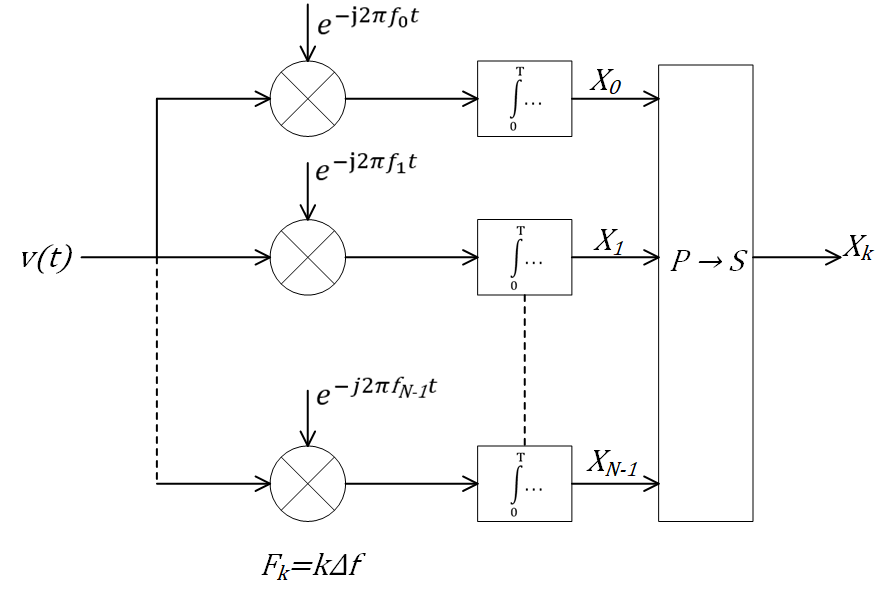
* OFDM demodulation
The orthogonal frequency division multiplexing (OFDM) method demodulates the OFDM input signal using an FFT operation, resulting in N parallel data streams.
The figure shows an OFDM demodulator consisting of a bank of N correlators with one correlator assigned to each OFDM subcarrier. The bank of correlators is followed by a parallel-to-serial conversion.
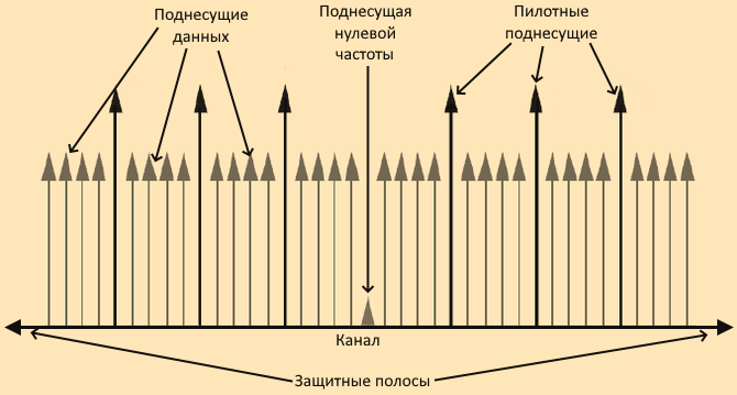
Subcarrier allocation, guard bands and guard intervals
Individual OFDM subcarriers are allocated as data, pilot or null subcarriers.
As shown here, the subcarriers are labelled as data, DC, pilot or guard band subcarriers.
-
Data subcarriers carry user data.
-
Pilot subcarriers are for channel evaluation.
-
Zero frequency subcarriers do not transmit any data. Non-data subcarriers provide the zero frequency centre subcarrier and serve as buffers between OFDM resource blocks.
-
The zero frequency subcarrier is the centre of the frequency band with an index of
if the value is even.
If is odd.
- is the total number of subcarriers in the OFDM signal.
-
The guard bands serve as a buffer between neighbouring signals in adjacent frequency bands to reduce interference caused by spectral leakage.
-
Zero frequency subcarriers allow modelling of guard bands and zero subcarrier locations for specific standards such as various 802.11 formats, LTE, WiMAX, or custom allocations. The location of the null subcarriers can be defined by assigning a vector of null subcarrier indices.
Similar to guard bands, guard intervals protect the integrity of transmitted signals in OFDM by reducing intersymbol interference.
The purpose of guard intervals is similar to that of guard bands. You can model guard intervals to provide temporal separation between OFDM symbols. Guard intervals help maintain inter-symbol orthogonality after a signal passes through time-dispersive channels. Guard intervals are created using cyclic prefixes. Inserting a cyclic prefix copies the last OFDM as the first part of the OFDM symbol.
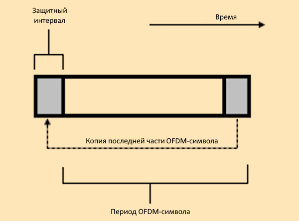
OFDM benefits from the usage of cyclic prefix insertion as long as the time variance does not exceed the duration of the cyclic prefix.
Insertion of the cyclic prefix results in a fractional reduction in user data throughput because the cyclic prefix takes up bandwidth that could have been used for data transmission.
Literature
-
Dahlman, E., S. Parkvall, and J. Skold. "4G LTE/LTE-Advanced for Mobile Broadband." London: Elsevier Ltd., 2011.
-
Andrews, J. G., A. Ghosh, and R. Muhamed. "Fundamentals of WiMAX. Upper Saddle River," NJ: Prentice Hall, 2007.
-
IEEE Standard 802.16-2017. "Part 16: Air Interface for Broadband Wireless Access Systems." March 2018.