EngeeComms.OFDMModulatorBaseband
Modulation using the OFDM method.
| Library |
|
| Block |
Description
The system object EngeeComms.OFDMModulatorBaseband modulates a signal in the frequency domain using the orthogonal frequency division multiplexing (OFDM) method. The output is a basic representation of the OFDM-modulated signal.
For more information, see. Orthogonal Frequency Division Multiplexing. The output is the basic representation of the OFDM modulated signal.
To modulate the signal using OFDM, follow the steps below:
-
Create an
EngeeComms.OFDMModulatorBasebandobject and set its properties. -
Call the object with arguments as if it were a function. To learn more about how system objects work, see Engee System Objects.
Syntax
Creation
-
ofdmMod = EngeeComms.OFDMModulatorBaseband()creates an OFDM modulator with by default property values.Example:
ofdmMod = EngeeComms.OFDMModulatorBaseband() -
ofdmMod = EngeeComms.OFDMModulatorBaseband(Name=Value)creates an OFDM modulator with each specified property Name (name) set to the specified Value (value). You can specify additional arguments as a name-value pair in any order (Name1=Value1,…,NameN=ValueN).Example:
ofdmMod = EngeeComms.OFDMModulatorBaseband(Windowing=true, NumGuardBandCarriers=[4; 2])
Usage
-
Y = ofdmMod(X)modulates the input data subcarriers in the frequency domain using the OFDM method and returns an OFDM-modulated baseband signal. -
Y = ofdmMod(data,pilot)assigns the pilot signal,pilot, to the frequency subcarriers specified by the indices of the PilotCarrierIndices property. To enable this syntax, set the property for the PilotInputPort property totrue.
Arguments
Input arguments
X -
input broadband signal
array
Details
Input broadband signal specified as an array to to .
-
- Is the number of subcarriers of the data.
-
- is the number of symbols defined by the NumSymbols property.
-
- the number of receive antennas defined by the NumTransmitAntennnas property.
| Data types |
|
| Support for complex numbers |
Yes |
pilot -
pilot signal
array
Details
Pilot signal specified as an array to to .
-
- the number of pilot subcarriers in each symbol defined by
size(PilotCarrierIndices,1). -
- the number of symbols defined by the NumSymbols property.
-
- number of transmitting antennas defined by the NumTransmitAntennnas property.
| Data types |
|
| Support for complex numbers |
Yes |
Output arguments
Y -
OFDM modulated broadband output signal
matrix
Details
OFDM modulated broadband signal returned as a matrix to of the same data type as the input signal.
-
- The oversampling factor, defined by the OversamplingFactor property.
-
= + ( * ).
-
- length of the cyclic prefix over all characters.
-
- the length of the cyclic prefix, defined by the CyclicPrefixLength parameters.
-
If CyclicPrefixLength is a scalar, .
-
If CyclicPrefixLength is a vector of strings, .
-
-
- The number of subcarriers defined by the FFTLength parameters.
-
- number of symbols, defined by the NumSymbols parameters.
-
- number of transmit antennas, defined by the NumTransmitAntennnas parameters.
| Data types |
|
| Support for complex numbers |
Yes |
Properties
FFTLength -
number of FFT points
64 (by default) | `positive integer `
Details
The number of Fast Fourier Transform (FFT) points specified as a positive integer scalar. The length of the FFT must be and equivalent to the number of subcarriers.
NumGuardBandCarriers -.
number of subcarriers allocated to the left and right guard bands
[6; 5] (by default) | Enumeric vector 2 by 1
Details
The number of subcarriers allocated to the left and right guard bands, given as a 2-by-1 integer vector.
The number of subcarriers of the left and right guard bands, , shall be within , where is the total number of subcarriers in the OFDM signal as determined by the FFTLength property.
InsertDCNull -
exclude or include the zero frequency subcarrier
false or 0 (by default) | true or 1
Details
Select this check box to delete the zero frequency subcarrier. The DC zero subcarrier is located in the centre of the frequency band and has an index value:
-
, if the value of is even.
-
, if the value of is odd.
- is the total number of subcarriers in the OFDM signal defined by the FFTLength property.
PilotInputPort -
pilot subcarrier input
false or 0 (by default) | true or 1
Details
Usage of the argument for pilot subcarrier input, given as a numeric or logical value 0 (false) or 1 (true).
-
false(0) - the input data argument, X, may contain embedded pilot subcarrier information, but the block does not assign pilot subcarrier indices. -
true(1) - the block assigns the subcarriers specified by the PilotCarrierIndices property to the pilot modulation signal in the pilot input argument.
PilotCarrierIndices — pilot subcarrier location indices
[12; 26; 40; 54] (by default) | column vector | matrix | 3D array
Details
Pilot subcarrier location indices specified as a column vector, matrix or array with integer element values in the range of
,
where:
-
- total number of subcarriers in the OFDM signal, defined by the parameters FFT length.
-
and - left and right guard bands, defined by the value of the Number of guard bands parameter.
The pilot carrier indices can be assigned the same or different subcarriers for each symbol and for all transmitting antennas .
-
If the pilot indices are the same for each symbol and transmitting antenna, the parameters have the dimension by 1.
-
If the pilot indices are different for each symbol, the parameters have the dimension by .
-
If the received signal is assigned one symbol on several transmitting antennas, the parameters has the dimension by 1 to .
-
If the indices differ in the number of symbols and transmitting antennas, the parameters have the dimension to to .
| To minimise interference between transmissions to more than one transmitting antenna, the pilot indices per symbol should be mutually different for all antennas. |
Dependencies
To use this property, set the PilotInputPort property to 1.
CyclicPrefixLength -.
cyclic prefix length
16 (by default) | positive integer | vector-string | vector-string
Details
The length of the cyclic prefix for each OFDM character, specified as a positive integer scalar or string vector containing the number of OFDM character elements. When specifying the length of the cyclic prefix as:
-
Scalar- the length of the cyclic prefix is the same for all symbols through all antennas. -
Vector-string- the length of the cyclic prefix can vary between symbols, but does not vary between antennas.
Windowing -
application of windowing function of increased cosine between OFDM symbols
false or 0 (by default) | true or 1
Details
Enables the window function of increased cosine between OFDM characters, set as numeric or logical 0 (false) or 1 (true).
To reduce the power of out-of-band subcarriers caused by spectral sprawl, apply windowing.
WindowLength -
length of window function with increased cosine
1 (by default) | positive integer
Details
Specify the length of the raised cosine window function as a positive integer scalar.
This value must be less than or equal to the minimum cyclic prefix length specified in the CyclicPrefixLength property. For example, in a four-character configuration with cyclic prefix lengths of 12, 14, 16, and 18, WindowLength must be less than or equal to 12.
Dependencies
To use this property, set the Windowing property to true.
OversamplingFactor -
oversampling factor
1 (by default) | positive integer
Details
The oversampling factor specified as a positive scalar. The oversampling factor must satisfy these constraints:
-
The product of OversamplingFactor by FFTLength must be an integer.
-
The product of OversamplingFactor over CyclicPrefixLength must be an integer.
If OversamplingFactor is specified as an irrational number, specify a fractional value. For example, given FFTLength 12 and OversamplingFactor 4/3, their product is the integer 16. However, rounding 4/3 to 1,333 when OversamplingFactor is set results in a non-integer product of 15,9960, which causes an error.
|
NumSymbols -
number of OFDM characters
1 (by default) | positive integer
Details
The number of OFDM characters in the time-frequency grid, specified as a positive integer scalar.
NumTransmitAntennnas -
number of transmitting antennas
1 (by default) | positive integer
Details
The number of transmit antennas for transmitting OFDM modulated signal is set as a positive integer scalar, 64.
Optional
Algorithms
Orthogonal frequency division multiplexing
OFDM belongs to the class of multicarrier modulation schemes. Due to the fact that multiple carriers can be transmitted simultaneously during operation, noise does not affect OFDM to the same extent as in single-band modulation.
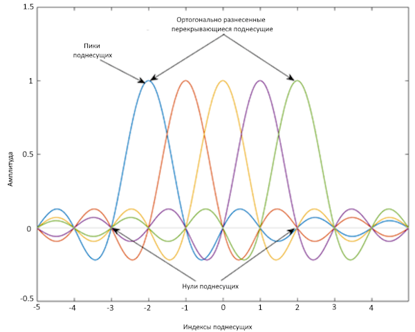
OFDM divides a high-speed data stream into low-speed data sub-streams by decomposing the transmission bandwidth into a number of contiguous individually modulated sub-carriers. This set of parallel and orthogonal subcarriers carries the data stream, occupying nearly the same bandwidth as a wideband channel. Through the usage of narrow orthogonal subcarriers, the OFDM signal becomes immune to hiccups in the frequency selective channel and eliminates interference from neighbouring subcarriers. Inter-symbol interference (ISI) is reduced because subflows with lower data rates have symbol durations longer than the channel delay spread.
This image shows the representation of orthogonal subcarriers in the frequency domain in OFDM waveform.
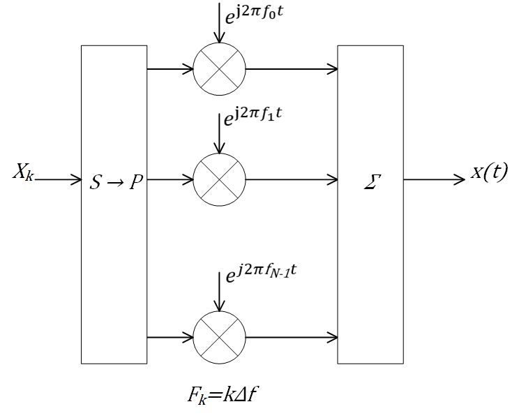
The transmitter applies the inverse fast Fourier transform (IFFT) to N symbols at a time. Typically, the output of the IFFT is the sum of N orthogonal sine waves:
,
where
-
- data symbols,
-
- OFDM symbol time.
The data symbols Xk are usually complex and can be from any digital modulation alphabet (e.g. QPSK, 16-QAM, 64-QAM, etc.).
| The discrete Fourier transform implementation normalises the IFFT output to . |
The subcarrier spacing is [Δf = 1/T], which ensures that the subcarriers are orthogonal during each symbol period:
The OFDM modulator consists of a series-parallel transform followed by a bank of N complex modulators individually corresponding to each OFDM subcarrier.
Subcarrier allocation, guard bands and guard intervals
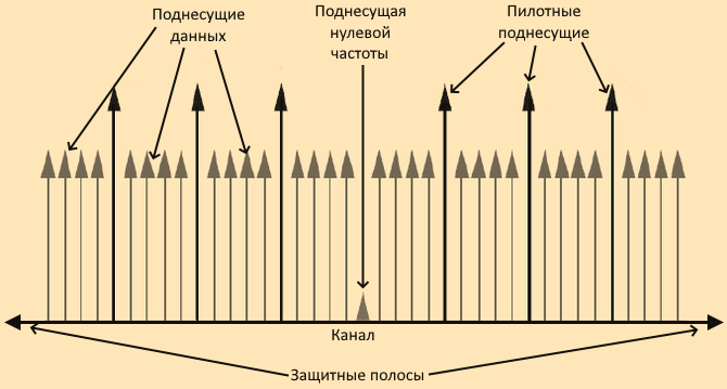
Individual OFDM subcarriers are allocated as data, pilot or null subcarriers.
As shown here, subcarriers are labelled as data, DC, pilot or guard band subcarriers.
-
Data subcarriers transmit user data.
-
Pilot subcarriers are used for channel evaluation.
-
Zero frequency subcarriers do not transmit any data. Non-data subcarriers provide the centre subcarrier zero frequency and serve as buffers between OFDM resource blocks.
-
The zero frequency subcarrier is the centre of the frequency band with an index of
if the value is even.
If is odd.
- is the total number of subcarriers in the OFDM signal.
-
The guard bands serve as a buffer between neighbouring signals in adjacent frequency bands to reduce interference caused by spectral leakage.
-
Zero frequency subcarriers allow modelling of guard bands and zero subcarrier locations for specific standards such as various 802.11 formats, LTE, WiMAX, or custom allocations. The location of the null subcarriers can be defined by assigning a vector of null subcarrier indices.
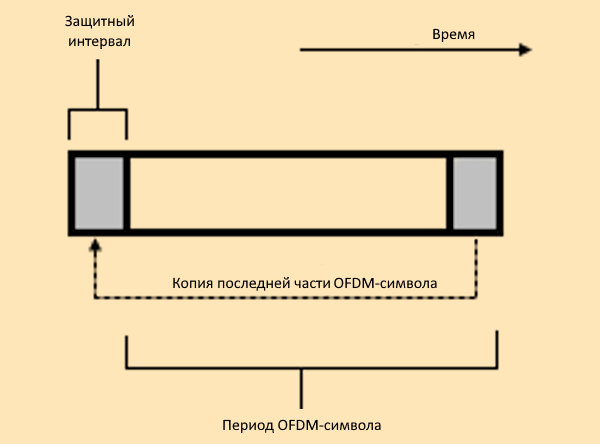
Similar to guard bands, guard intervals protect the integrity of transmitted signals in OFDM by reducing intersymbol interference.
The purpose of guard intervals is similar to that of guard bands. You can model guard intervals to provide temporal separation between OFDM symbols. Guard intervals help maintain inter-symbol orthogonality after a signal passes through time-dispersive channels. Guard intervals are created using cyclic prefixes. Inserting a cyclic prefix copies the last OFDM as the first part of the OFDM symbol.
OFDM benefits from the usage of cyclic prefix insertion as long as the time variance does not exceed the duration of the cyclic prefix.
Insertion of the cyclic prefix results in a fractional reduction in user data throughput because the cyclic prefix takes up bandwidth that could have been used for data transmission.
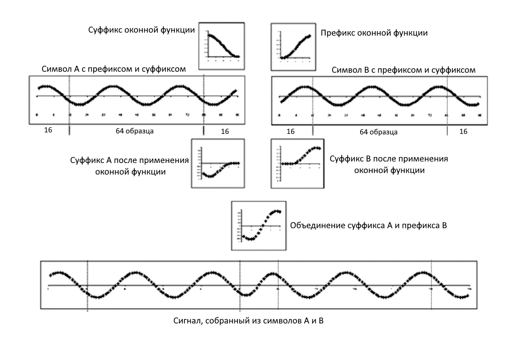
*Window function for OFDM with increased cosine.
The window function for OFDM with increased cosine applies the techniques described in [3] to limit spectral sprawl by creating a smooth transition between the last sample of one symbol and the first sample of the next symbol.
Although the cyclic prefix creates a guard period in the time domain to preserve orthogonality, an OFDM symbol rarely starts with the same amplitude and phase as at the end of the previous OFDM symbol, causing spectral sprawl and hence signal bandwidth expansion due to intermodulation distortion. To limit this spectral sprawl, a smooth transition can be created between the last sample of a symbol and the first sample of the next symbol using a cyclic suffix and a window function with an increased cosine.
To create a cyclic suffix, the operation adds the first samples ) of a given symbol to the end of that symbol. However, to comply with IEEE® 802.11g, for example, the operation cannot arbitrarily lengthen a symbol. Instead, the cyclic suffix must overlap in time and effectively sum to the cyclic prefix of the next symbol. The operation applies two, mathematically inverse, window functions to this overlapping segment. The first windowing function with increased cosine is applied to the cyclic suffix of symbol k and decreases from 1 to 0 over its lifetime. The second window function with increased cosine is applied to the cyclic prefix of symbol k+1 and increases from 0 to 1 over its lifetime. This process provides a smooth transition from one symbol to the next.
The window function with increased cosine, , in the time domain can be expressed as:
,
where:
-
- OFDM symbol duration, including guard interval.
-
- duration of the window function.
The cyclic suffix length is adjusted by setting the window function length, with the suffix length set between 1 and the minimum cyclic prefix length. Although windowing improves spectral recovery, this comes at the expense of reduced immunity to multipath hiccups due to reduced redundancy in the guard band due to changing guard band sampling values to realise inter-symbol transition smoothing.
These figures show the application of the window function with increased cosine.
Literature
-
Dahlman, E., S. Parkvall, and J. Skold. "4G LTE/LTE-Advanced for Mobile Broadband." London: Elsevier Ltd., 2011.
-
Andrews, J. G., A. Ghosh, and R. Muhamed. "Fundamentals of WiMAX." Upper Saddle River, NJ: Prentice Hall, 2007.
-
Agilent Technologies, Inc., "OFDM Raised Cosine Windowing," https://helpfiles.keysight.com/csg/n7617/Content/Main/ofdm_raised_cosine_windowing.htm.
-
Montreuil, L., R. Prodan, and T. Kolze. "OFDM TX Symbol Shaping 802.3bn," https://www.ieee802.org/3/bn/public/jan13/montreuil_01a_0113.pdf. Broadcom, 2013.
-
IEEE Standard 802.16-2017. "Part 16: Air Interface for Broadband Wireless Access Systems." March 2018.