Schmitt Trigger
The behavioral model of the Schmitt trigger.
blockType: AcausalElectricPowerSystems.IntegratedCircuits.Logic.SchmittTrigger
|
Path in the library: |

Description
Block Schmitt Trigger implements the behavioral model of the Schmitt trigger.
The output logic level of the block becomes HIGH when the input signal rises above the parameter value High level input voltage, and does not switch to LOW until the input signal drops below the parameter value Low level input voltage. This logic generates a hysteresis characteristic of the dependence of the output signal on the input signal.
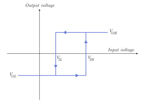
The figure shows the input signal to the trigger for which and correspond to the values of the parameters High level input voltage and Low level input voltage, and correspond to the values of the parameters High level output voltage and Low level output voltage.
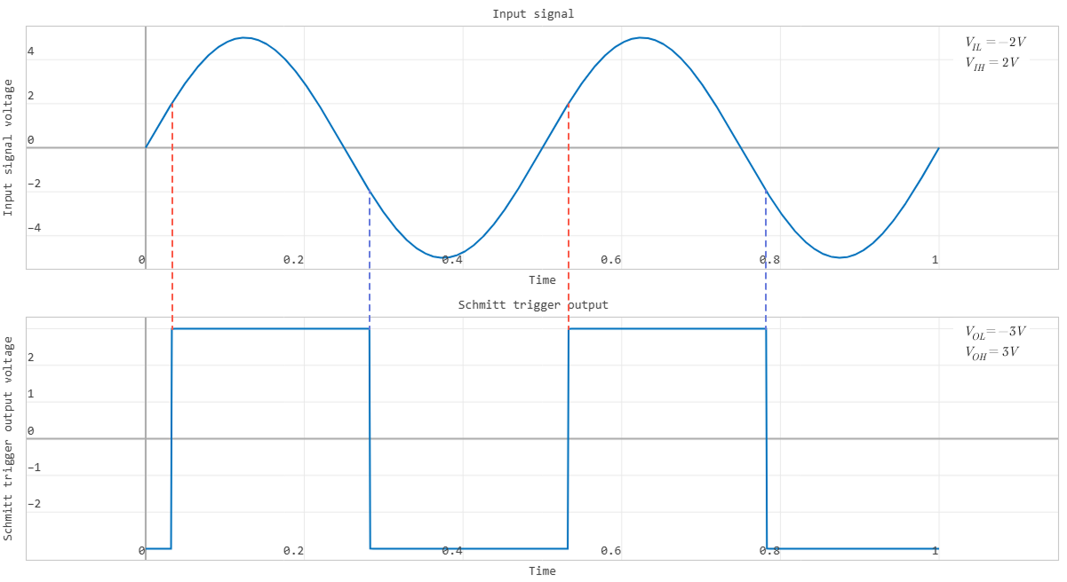
The following figure shows an example of the output signal of a block with parameters In, In, In and V.
The block defines the logical input levels as follows:
-
If the input voltage is higher than the threshold, the unit interprets the input signal as a logic
1. -
Otherwise, the block interprets the input signal as logical.
0.
The threshold voltage is equal to the average value of the parameters High level input voltage and Low level input voltage.
| To increase the simulation speed, the unit does not simulate each internal MOSFET device of the gate individually. For more information, see [assumptions-and-limits]. |
The block simulates the shutter as follows:
-
Gate inputs have infinite resistance and finite or zero capacitance.
-
One of two models can be selected for the shutter output signal:
LinearorQuadratic. The output model is set by the parameter Output current-voltage relationship. -
Propagation delay can be set for both output models. For the model
Linearthe block sets the value of the gate output capacitor so that the resistive-capacitive time constant is equal to the value of the parameter Propagation delay. For the modelQuadraticThe input signal of the shutter is delayed to approximately match the value of the parameter Propagation delay.
The output voltage of the unit depends on the selected output model:
-
For the model
LinearThe high output voltage level corresponds to the value of the parameter High level output voltage, and the low level of the output voltage corresponds to the value of the parameter Low level output voltage. -
For the model
Quadraticoutput voltage in statesHIGHandLOWIt is a function of the output current. At zero load current, the high output voltage level is , that is , the value of the parameter Supply voltage, and the low output voltage level is zero volts.
Assumptions and limitations
The unit does not simulate each internal MOSFET device of the gate individually, unless for the parameter Output current-voltage relationship the value is not set Quadratic then the exception is the last pair of MOSFET devices. This limitation has the following consequences:
-
The unit inaccurately simulates the gate’s response to input noise and input signals close to the logical threshold voltage.
-
The block inaccurately models the dynamic response.
For feedback circuits around a set of logic gates, it may be necessary to set a non-zero propagation delay for one or more gates.
This block is implemented using event equations. Therefore, it is necessary to set the initial output state corresponding to the input signal of the block at the initial time. For example, if the initial output state is HIGH, and the initial input voltage is lower than the value of the parameter Low level input voltage, then the initial value of the output will remain in the state HIGH. The state will change only after the input voltage rises above the parameter value. High level input voltage.
Parameters
Outputs
#
Protection diode forward voltage —
forward voltage of the protective diode
V | uV | mV | kV | MV
Details
The voltage that triggers the protective diode when exceeded.
Dependencies
To use this parameter, set for the parameter Output current-voltage relationship meaning Quadratic.
| Units |
|
| Default value |
|
| Program usage name |
|
| Evaluatable |
Yes |
#
Propagation delay —
propagation delay
s | ns | us | ms | min | hr | d
Details
The time required to change the output signal from the state LOW in the state of HIGH or out of the state HIGH in the state of LOW after changing the input logic levels.
| Units |
|
| Default value |
|
| Program usage name |
|
| Evaluatable |
Yes |
#
Measurement voltage —
Measuring voltage
V | uV | mV | kV | MV
Details
The gate supply voltage at which the output resistances and currents are set.
Dependencies
To use this parameter, set for the parameter Output current-voltage relationship meaning Quadratic.
| Units |
|
| Default value |
|
| Program usage name |
|
| Evaluatable |
Yes |
#
Output resistance —
output resistance
Ohm | mOhm | kOhm | MOhm | GOhm
Details
The value of the serial output resistor used to simulate the output voltage drop caused by the output current. This value can be obtained from the technical description by dividing the high-level output voltage by the maximum low-level output current.
Dependencies
To use this parameter, set for the parameter Output current-voltage relationship meaning Linear.
| Units |
|
| Default value |
|
| Program usage name |
|
| Evaluatable |
Yes |
#
Low level output voltage —
low-level output voltage
V | uV | mV | kV | MV
Details
The value of the output voltage when the logical level of the output signal is LOW.
Dependencies
To use this parameter, set for the parameter Output current-voltage relationship meaning Linear.
| Units |
|
| Default value |
|
| Program usage name |
|
| Evaluatable |
Yes |
#
High level output voltage —
high-level output voltage
V | uV | mV | kV | MV
Details
The value of the output voltage when the logical level of the output signal is HIGH.
Dependencies
To use this parameter, set for the parameter Output current-voltage relationship meaning Linear.
| Units |
|
| Default value |
|
| Program usage name |
|
| Evaluatable |
Yes |
#
Logic HIGH output current I_OH when shorted to ground —
Output current high level in case of ground fault
A | pA | nA | uA | mA | kA | MA
Details
The resulting current when the logical level of the output signal is HIGH but the load causes the output voltage to tend to zero.
Dependencies
To use this parameter, set for the parameter Output current-voltage relationship meaning Quadratic.
| Units |
|
| Default value |
|
| Program usage name |
|
| Evaluatable |
Yes |
#
Logic LOW output current I_OL when shorted to Vcc —
Output current low level when shorted to
A | pA | nA | uA | mA | kA | MA
Details
The resulting current when the logical level of the output signal is LOW but the load causes the output voltage to tend to the supply voltage .
Dependencies
To use this parameter, set for the parameter Output current-voltage relationship meaning Quadratic.
| Units |
|
| Default value |
|
| Program usage name |
|
| Evaluatable |
Yes |
#
Logic HIGH output resistance at zero current and at I_OH —
the resistance of the high logical level of the output signal at zero current and at
Ohm | mOhm | kOhm | MOhm | GOhm
Details
Resistance at the logical level of the output signal HIGH. Set the value for this parameter as a vector, a string of two resistance values. , where — the gradient of the dependence of the output voltage on the current in the absence of an output current, and — the gradient of the dependence of the output voltage on the current at the output current .
Dependencies
To use this parameter, set for the parameter Output current-voltage relationship meaning Quadratic.
| Units |
|
| Default value |
|
| Program usage name |
|
| Evaluatable |
Yes |
#
Output current-voltage relationship —
the model of the dependence of the output current on the voltage
Linear | Quadratic
Details
A model that determines the dependence of the output current on the output voltage. Set this parameter to Linear or Quadratic.
| Values |
|
| Default value |
|
| Program usage name |
|
| Evaluatable |
No |
#
Logic LOW output resistance at zero current and at I_OL —
the resistance of the low logic level of the output signal at zero current and at
Ohm | mOhm | kOhm | MOhm | GOhm
Details
Resistance at the logical level of the output signal LOW. Set the value for this parameter as a vector, a string of two resistance values. , where — the gradient of the dependence of the output voltage on the current in the absence of an output current, and — the gradient of the dependence of the output voltage on the current at the output current .
Dependencies
To use this parameter, set for the parameter Output current-voltage relationship meaning Quadratic.
| Units |
|
| Default value |
|
| Program usage name |
|
| Evaluatable |
Yes |
#
Supply voltage —
Supply voltage
V | uV | mV | kV | MV
Details
The voltage that is applied to the gate in the circuit.
Dependencies
To use this parameter, set for the parameter Output current-voltage relationship meaning Quadratic.
| Units |
|
| Default value |
|
| Program usage name |
|
| Evaluatable |
Yes |
#
Protection diode on resistance —
resistance of an open protective diode
Ohm | mOhm | kOhm | MOhm | GOhm
Details
The voltage-current gradient for forward-biased protective diodes.
Dependencies
To use this parameter, set for the parameter Output current-voltage relationship meaning Quadratic.
| Units |
|
| Default value |
|
| Program usage name |
|
| Evaluatable |
Yes |
Initial Conditions
#
Output initial state —
initial state of the output signal
Low | High
Details
The initial state of the block output signal can take the values High or Low. This parameter is used for both linear and quadratic output models, provided that the value of the parameter Propagation delay more 0 and in the block Solver Configuration the checkbox is not checked Start simulation from steady state.
| Values |
|
| Default value |
|
| Program usage name |
|
| Evaluatable |
No |
Inputs
#
High level input voltage —
high-level input voltage
V | uV | mV | kV | MV
Details
The input voltage above which the unit interprets the input signal as logical HIGH.
| Units |
|
| Default value |
|
| Program usage name |
|
| Evaluatable |
Yes |
#
Low level input voltage —
low-level input voltage
V | uV | mV | kV | MV
Details
The input voltage below which the unit interprets the input signal as logical LOW.
| Units |
|
| Default value |
|
| Program usage name |
|
| Evaluatable |
Yes |
#
Average input capacitance —
average input capacity
F | pF | nF | uF | mF
Details
A fixed capacity approximately corresponding to the input capacity of the MOSFET gate. The MOSFET capacity depends on the applied voltage. If this unit is controlled by another shutter, the parameter Average input capacitance provides a rise time similar to the rise time of a MOSFET. The value of this capacity can be found in the manufacturer’s technical description. To speed up the simulation, set this parameter to 0.
| Units |
|
| Default value |
|
| Program usage name |
|
| Evaluatable |
Yes |