N-Channel MOSFET
A model of an n-channel or p-channel MOSFET based on surface potential equations.
blockType: AcausalElectricPowerSystems.Semiconductors.MOSFET
|
N-Channel MOSFET Path in the library: |
|
P-Channel MOSFET Path in the library: |


Description
Blocks N-Channel MOSFET and P-Channel MOSFET An n-channel or p-channel field-effect transistor with a metal-oxide-semiconductor (MOSFET) structure is modeled based on surface potential equations.
The block also has the ability to simulate thermal effects.
A model based on surface potential equations
The model based on the surface potential equations takes into account the following effects:
-
A fully nonlinear capacity model (including Miller’s nonlinear capacity).
-
Saving the charge.
-
Saturation of media speed and channel length modulation.
-
Built-in diode.
-
Reverse recovery in the built-in diode model.
-
Influence of temperature on physical parameters.
-
Dynamic self-heating for the option of modeling thermal effects (modeling the effect of self-heating on the electrical characteristics of the device).
This model is a simplified version of the standard PSP model [1], including only some of it in order to find a balance between accuracy and complexity of the model. For more information about the physical prerequisites of the phenomena included in this model, see [2].
The following are the surface potential equations for an n-channel MOSFET. The equations for a p-channel MOSFET are derived similarly, but charges and currents are multiplied by -1.
The model is based on the Poisson equation:
where
-
— electrostatic potential;
-
— electron charge;
-
— the concentration of acceptors in the substrate;
-
— the dielectric constant of a semiconductor material (for example, silicon);
-
— the difference between the intrinsic Fermi level and the Fermi level of bulk silicon;
-
is the quasi—Fermi potential of the surface layer with respect to the bulk;
-
— temperature potential;
-
— Boltzmann constant;
-
— temperature.
The Poisson equation is used to obtain the surface potential equation:
where
-
— applied gate-substrate voltage;
-
— flat zone voltage;
-
— surface potential;
-
— the coefficient of the substrate:
-
— specific surface capacity.
The block uses an explicit approximation of the surface potential equation to avoid the need for a numerical solution to this implicit equation.
After the surface potential is known, the drain current It is defined as follows
where
-
— device width;
-
— channel length;
-
— mobility in weak fields;
-
— saturation of the speed;
-
— the difference in surface potentials between the drain and the source;
-
and — the density of the inversion charge at the source and drain , respectively;
-
— the average density of the inversion charge along the channel;
-
— the coefficient of reduction of mobility. For more information, see the parameter description. Surface roughness scattering factor;
-
— channel length modulation:
where
-
— channel length modulation coefficient;
-
— drain-substrate voltage;
-
— drain-substrate voltage, trimmed to the maximum value corresponding to saturation of the velocity or cut-off (whichever comes first);
-
— channel length modulation voltage.
-
The unit calculates the inversion charge densities directly from the surface potential.
The unit also calculates nonlinear capacitances from the surface potential. The contributions of the source and sink charges are assigned using the Ward-Dutton charge separation scheme, which depends on displacement, as described in [3]. These charges are calculated explicitly, so charges are conserved in this model. The capacitive currents are calculated by taking the time derivatives of the corresponding charges. In practice, the charges in the simulation are normalized to the oxide capacity and calculated in volts.
MOSFET gain It is defined as follows:
The threshold voltage for a source-substrate short-circuit connection is approximately determined as follows:
where — surface potential with strong inversion.
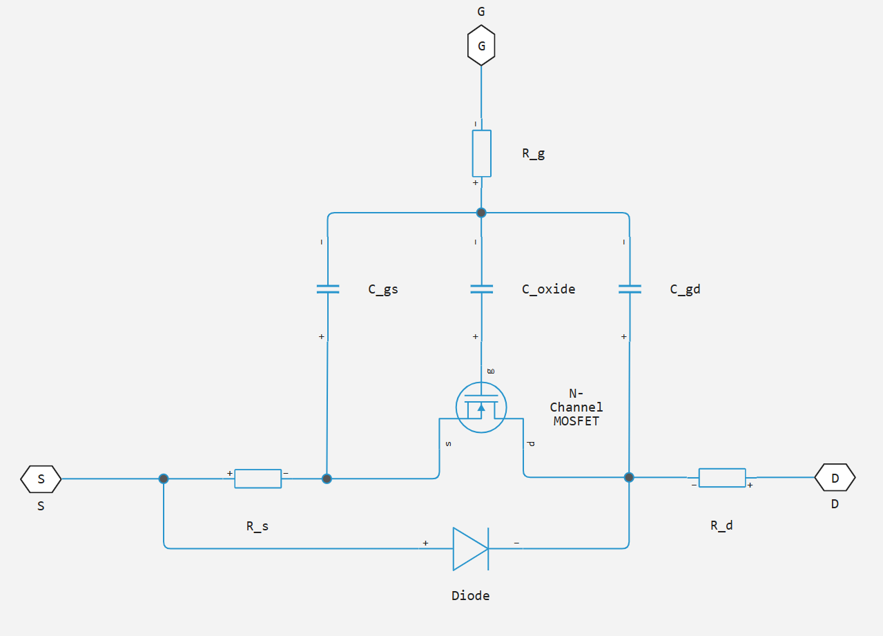
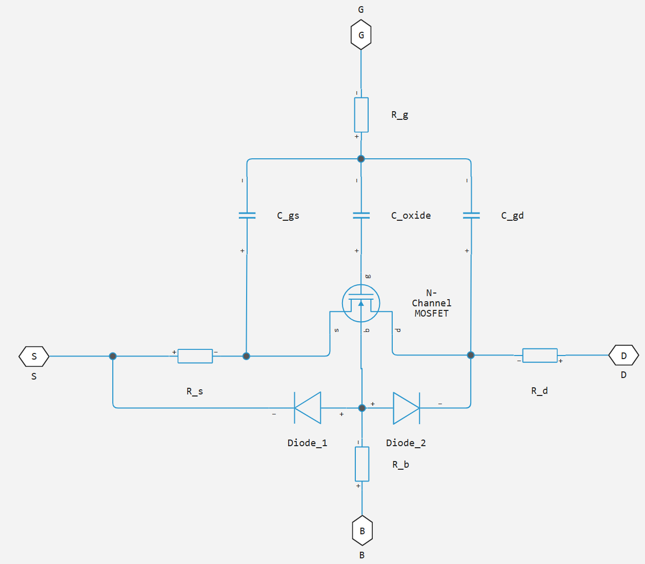
In general, three- and four-channel models consist of their own MOSFET, defined by the surface potential formula, an integrated diode, series resistances, and fixed junction capacitances, as shown in the diagram for an n-channel MOSFET.
Simulation of the built-in diode
The unit simulates an integrated diode with an exponential volt-ampere characteristic (VAC).
The junction capacity and diffusion capacity are calculated as:
where
-
— current through the diode;
-
— reverse saturation current;
-
— drain-substrate voltage;
-
— the coefficient of perfection;
-
— temperature potential;
-
— diode junction capacity;
-
— transition capacity at zero offset;
-
— voltage of the built-in diode;
-
— diffusion capacity of the diode;
-
— time of passage.
Modeling of temperature dependence
By default, temperature dependence is ignored, and the device is modeled at the temperature for which the parameters are set. To take into account the temperature dependence during the simulation, set the parameter Parameterization meaning Model temperature dependence.
The model based on the surface potential equations takes into account the influence of temperature on the capacitive characteristics, and also simulates the dependence of the static behavior of the transistor on temperature during the simulation.
Parameter Measurement temperature detects the temperature , in which some device parameters are set. Parameters in the section Temperature Dependence set the simulation temperature and the coefficients of temperature dependence for the rest of the device parameters.
Thermal port
The unit has an additional thermal port, hidden by default. To use the thermal port H, check the box Enable thermal port.
Use the thermal port to simulate the effects of generated heat and device temperature.
Variables
Use the parameter group Initial Targets to set the priority and initial target values for the block parameter variables before modeling. For more information, see Configuring physical blocks using target values.
Ports
Conserving
#
g
—
the shutter
electricity
Details
The port connected to the gate.
| Program usage name |
|
#
d
—
stock
electricity
Details
The port associated with the drain.
| Program usage name |
|
#
s
—
the source
electricity
Details
The port associated with the source.
| Program usage name |
|
#
H
—
thermal port
warm
Details
The thermal port.
Dependencies
To use this port, check the box Enable thermal port.
| Program usage name |
|
#
b
—
body
electricity
Details
The port connected to the built-in diode on the substrate.
Dependencies
To use this port, set the parameter Number of terminals meaning Four.
| Program usage name |
|
Parameters
Main
#
Transistor type —
transistor type
N-Channel | P-Channel
Details
Transistor Model Type:
-
N-Channel— n-channel MOSFET; -
P-Channel— p-channel MOSFET.
| Values |
|
| Default value |
|
| Program usage name |
|
| Evaluatable |
No |
#
Number of terminals —
parameterization of contacts
Three | Four
Details
The number of contacts in the block.
| Values |
|
| Default value |
|
| Program usage name |
|
| Evaluatable |
No |
#
Gain —
gain
A/V^2
Details
MOSFET gain . This parameter primarily defines the linear area on the characteristic - .
| Units |
|
| Default value |
|
| Program usage name |
|
| Evaluatable |
Yes |
#
Flatband voltage —
flat zone voltage
V | uV | mV | kV | MV
Details
Flat zone voltage determines the gate offset that must be applied to achieve a flat zone state on the silicon surface. You can use this parameter to arbitrarily shift the threshold voltage due to differences in the output of materials, as well as trapped charges at the interface or oxide. However, in practice, it is usually recommended to first change the threshold voltage using the parameters Body factor and Surface potential at strong inversion, and use this parameter only for fine-tuning.
| Units |
|
| Default value |
|
| Program usage name |
|
| Evaluatable |
Yes |
#
Body factor —
substrate ratio
V^(1/2) | MV^(1/2) | kV^(1/2) | mV^(1/2)
Details
The substrate factor in the equation of the surface potential. This parameter primarily affects the threshold voltage.
| Units |
|
| Default value |
|
| Program usage name |
|
| Evaluatable |
Yes |
#
Surface potential at strong inversion —
surface potential with strong inversion
V | uV | mV | kV | MV
Details
Value in the equation of the surface potential. This parameter also primarily affects the threshold voltage.
| Units |
|
| Default value |
|
| Program usage name |
|
| Evaluatable |
Yes |
#
Velocity saturation factor —
rate saturation coefficient
1/V | 1/MV | 1/kV | 1/mV
Details
Value in the drain current equation. Use this parameter in cases where good compliance with the linear mode results in too much saturation current. Increasing the value of this parameter leads to a decrease in the saturation current. For high-voltage devices, it often happens that good compliance with the linear mode leads to too low saturation current. In this case, the gain and ohmic resistance of the drain should be increased.
| Units |
|
| Default value |
|
| Program usage name |
|
| Evaluatable |
Yes |
# Channel-length modulation factor — channel length modulation coefficient
Details
Ratio , which is the multiplier of the logarithmic term in the equation for . This parameter describes the beginning of the channel length modulation. For the characteristics of a device that exhibits positive saturation conductivity, increase the parameter value to match this behavior. The default value is 0, which means the channel length modulation is disabled.
| Default value |
|
| Program usage name |
|
| Evaluatable |
Yes |
#
Channel-length modulation voltage —
channel length modulation voltage
V | uV | mV | kV | MV
Details
Voltage in the equation for . This parameter controls the drain voltage at which channel length modulation begins to operate.
| Units |
|
| Default value |
|
| Program usage name |
|
| Evaluatable |
Yes |
#
Surface roughness scattering factor —
scattering coefficient of surface roughness
1/V | 1/MV | 1/kV | 1/mV
Details
The power of reducing mobility. Mobility is equal to , where — mobility in weak fields without the influence of surface scattering. Coefficient of reduction of mobility defined as , where — the scattering coefficient of surface roughness, and is the voltage that corresponds to the effective vertical component of the electric field strength in the channel . For high vertical electric fields, the electron mobility is approximately proportional to .
| Units |
|
| Default value |
|
| Program usage name |
|
| Evaluatable |
Yes |
# Linear-to-saturation transition coefficient — linear region-saturation transition coefficient
Details
This coefficient characterizes the smooth transition of the MOSFET characteristic from the linear region to saturation, especially if speed saturation is enabled. This parameter can usually be left at the default value, but you can use it to fine-tune the bending characteristic. - . The expected range of values for this parameter is from 2 before 8.
| Default value |
|
| Program usage name |
|
| Evaluatable |
Yes |
#
Measurement temperature —
Measurement temperature
K | degC | degF | degR | deltaK | deltadegC | deltadegF | deltadegR
Details
Temperature , at which the block parameters are measured. If the parameter value is Device simulation temperature If it differs from this value, the device parameters will be determined according to the simulation temperature and the reference temperature.
| Units |
|
| Default value |
|
| Program usage name |
|
| Evaluatable |
Yes |
Ohmic Resistance
#
Source ohmic resistance —
transistor source resistance
Ohm | mOhm | kOhm | MOhm | GOhm
Details
The source resistance of the transistor, that is, the series resistance associated with the source contact. The value must be greater than or equal to 0.
| Units |
|
| Default value |
|
| Program usage name |
|
| Evaluatable |
Yes |
#
Drain ohmic resistance —
transistor drain resistance
Ohm | mOhm | kOhm | MOhm | GOhm
Details
The drain resistance of the transistor, that is, the series resistance associated with the drain contact. The value must be greater than or equal to 0.
| Units |
|
| Default value |
|
| Program usage name |
|
| Evaluatable |
Yes |
#
Gate ohmic resistance —
transistor gate resistance
Ohm | mOhm | kOhm | MOhm | GOhm
Details
The gate resistance of the transistor, that is, the series resistance associated with the gate contact. The value must be greater than or equal to 0.
| Units |
|
| Default value |
|
| Program usage name |
|
| Evaluatable |
Yes |
#
Bulk ohmic resistance —
resistance of the transistor substrate
Ohm | mOhm | kOhm | MOhm | GOhm
Details
The resistance of the transistor substrate, that is, the series resistance associated with the substrate contact.
Dependencies
To use this parameter, set for the parameter Number of terminals meaning Four.
| Units |
|
| Default value |
|
| Program usage name |
|
| Evaluatable |
Yes |
Channel Capacitances
#
Oxide capacitance —
oxide capacity
F | pF | nF | uF | mF
Details
The capacity between the gate and the channel.
| Units |
|
| Default value |
|
| Program usage name |
|
| Evaluatable |
Yes |
#
Gate-source overlap capacitance —
gate-source junction capacity
F | pF | nF | uF | mF
Details
Fixed linear capacitance associated with the gate-source junction.
| Units |
|
| Default value |
|
| Program usage name |
|
| Evaluatable |
Yes |
#
Gate-drain overlap capacitance —
gate-drain junction capacity
F | pF | nF | uF | mF
Details
Fixed linear capacity associated with the gate-drain junction.
| Units |
|
| Default value |
|
| Program usage name |
|
| Evaluatable |
Yes |
Body Diode
#
Reverse saturation current —
reverse saturation current
A | pA | nA | uA | mA | kA | MA
Details
Current in the equations for the built-in diode.
Set this parameter to a non-zero value to simulate the passage of current through the built-in diode, for applications where the MOSFET current changes sign during simulation, for example, when the MOSFET drives an inductive load.
For applications where the MOSFET current never changes sign, such as in a small-signal amplifier, set this parameter to 0 to increase the simulation speed.
| Units |
|
| Default value |
|
| Program usage name |
|
| Evaluatable |
Yes |
#
Built-in voltage —
voltage of the built-in diode
V | uV | mV | kV | MV
Details
Voltage of the built-in diode in the equations for the built-in diode. This voltage only affects the junction capacitance equation. It does not affect the conduction current.
| Units |
|
| Default value |
|
| Program usage name |
|
| Evaluatable |
Yes |
# Ideality factor — the coefficient of perfection
Details
The coefficient of perfection in the equations for the built-in diode.
| Default value |
|
| Program usage name |
|
| Evaluatable |
Yes |
#
Zero-bias junction capacitance —
transition capacity at zero offset
F | pF | nF | uF | mF
Details
The capacitance between the drain and the substrate at zero bias, due only to the built-in diode, in the equations for the built-in diode.
| Units |
|
| Default value |
|
| Program usage name |
|
| Evaluatable |
Yes |
#
Transit time —
Transit time
s | ns | us | ms | min | hr | d
Details
Time in the equations for the built-in diode.
If the parameter values are Reverse saturation current and Transit time If they are non-zero, then the block includes reverse recovery to the built-in diode model.
| Units |
|
| Default value |
|
| Program usage name |
|
| Evaluatable |
Yes |
Temperature Dependence
#
Parameterization —
parameterization of temperature dependence
None - Simulate at parameter measurement temperature | Model temperature dependence
Details
Choose one of the following methods for parameterizing the temperature dependence:
-
None - Simulate at parameter measurement temperature— temperature dependence is not modeled. This is the default method. -
Model temperature dependence— simulation of temperature-dependent effects. Specify the temperature value of the device simulation and the coefficients of temperature dependence for other block parameters.
| Values |
|
| Default value |
|
| Program usage name |
|
| Evaluatable |
No |
# Gain temperature exponent — an indicator of the degree of temperature dependence of the gain coefficient
Details
It is assumed that the gain of the MOSFET exponentially depends on temperature: , where — this is the parameter value Gain, and — parameter value Gain temperature exponent.
Dependencies
To use this parameter, set for the parameter Parameterization meaning Model temperature dependence.
| Default value |
|
| Program usage name |
|
| Evaluatable |
Yes |
#
Flatband voltage temperature coefficient —
coefficient in the temperature dependence of the voltage of the flat zone
V/K
Details
It is assumed that the voltage of the flat zone linearly dependent on temperature: , where — this is the parameter value Flatband voltage, and — this is the parameter value Flatband voltage temperature coefficient.
Dependencies
To use this parameter, set for the parameter Parameterization meaning Model temperature dependence.
| Units |
|
| Default value |
|
| Program usage name |
|
| Evaluatable |
Yes |
#
Surface potential at strong inversion temperature coefficient —
coefficient in the temperature dependence of the surface potential under strong inversion
V/K
Details
It is assumed that the surface potential under strong inversion linearly dependent on temperature: , where — this is the parameter value Surface potential at strong inversion, and — this is the parameter value Surface potential at strong inversion temperature coefficient.
Dependencies
To use this parameter, set for the parameter Parameterization meaning Model temperature dependence.
| Units |
|
| Default value |
|
| Program usage name |
|
| Evaluatable |
Yes |
# Velocity saturation temperature exponent — an indicator of the degree of temperature dependence of saturation velocity
Details
It is assumed that the saturation of the speed exponentially depends on temperature: , where — this is the parameter value Velocity saturation factor, and — parameter value Velocity saturation temperature exponent.
Dependencies
To use this parameter, set for the parameter Parameterization meaning Model temperature dependence.
| Default value |
|
| Program usage name |
|
| Evaluatable |
Yes |
# Surface roughness scattering temperature exponent — an indicator of the degree of temperature dependence of the scattering coefficient of surface roughness
Details
This parameter leads to a temperature-dependent decrease in the conductivity of the MOSFET at high gate voltage.
It is assumed that the scattering coefficient of the surface roughness exponentially depends on temperature: , where — this is the parameter value Surface roughness scattering factor, and — parameter value Surface roughness scattering temperature exponent.
Dependencies
To use this parameter, set for the parameter Parameterization meaning Model temperature dependence.
| Default value |
|
| Program usage name |
|
| Evaluatable |
Yes |
# Resistance temperature exponent — an indicator of the degree of temperature dependence of resistance
Details
It is assumed that the series resistances correspond to semiconductor resistances. Therefore, they decrease exponentially with increasing temperature.: , where — This is , or for the resistance of the source, drain or gate, respectively, — this is the value of the corresponding parameter Source ohmic resistance, Drain ohmic resistance or Gate ohmic resistance, and — parameter value Resistance temperature exponent.
Dependencies
To use this parameter, set for the parameter Parameterization meaning Model temperature dependence.
| Default value |
|
| Program usage name |
|
| Evaluatable |
Yes |
# Body diode reverse saturation current temperature exponent — an indicator of the degree of temperature dependence of the reverse saturation current
Details
It is assumed that the reverse saturation current for the built-in diode is proportional to the square of the concentration of its own carriers.: , where is the temperature—dependent effective density of states, and is the temperature—dependent band gap for a semiconductor material. In order not to introduce another parameter for the temperature dependence, the block neglects the temperature dependence of the band gap width and uses the silicon band gap at 300 K (1.12 eV) for all types of devices. Thus, the temperature dependence of the reverse saturation current is determined as follows:
where — parameter value Reverse saturation current, — Boltzmann constant, — parameter value Body diode reverse saturation current temperature exponent. The default value is 3 because for silicon, approximately proportionally . It is possible to take into account the temperature dependence of the band gap width by adjusting the value .
Dependencies
To use this parameter, set for the parameter Parameterization meaning Model temperature dependence.
| Default value |
|
| Program usage name |
|
| Evaluatable |
Yes |
#
Device simulation temperature —
Device simulation temperature
K | degC | degF | degR | deltaK | deltadegC | deltadegF | deltadegR
Details
Temperature , for which the device is being modeled.
Dependencies
To use this parameter, set for the parameter Parameterization meaning Model temperature dependence.
| Units |
|
| Default value |
|
| Program usage name |
|
| Evaluatable |
Yes |
Thermal Port
# Enable thermal port — turning on the heat port
Details
To enable the simulation of thermal effects, select the checkbox for this option.
| Default value |
|
| Program usage name |
|
| Evaluatable |
No |
#
Thermal network —
choosing an internal thermal model
Specify junction and case thermal parameters | Cauer model | Cauer model parameterized with Foster coefficients | External
Details
Choose an internal thermal model:
-
Specify junction and case thermal parameters; -
Cauer model; -
Cauer model parameterized with Foster coefficients; -
External.
| Values |
|
| Default value |
|
| Program usage name |
|
| Evaluatable |
No |
#
Junction-case and case-ambient (or case-heatsink) thermal resistances, [R_JC, R_CA] —
the vector of thermal resistances
K/W
Details
Vector [R_JC, R_CA] of the two values of thermal resistance. The first value R_JC — this is the thermal resistance between the junction and the housing. The second value, R_CA — this is the thermal resistance between the H port and the device body.
Dependencies
To use this parameter, set for the parameter Thermal network meaning Specify junction and case thermal parameters.
| Units |
|
| Default value |
|
| Program usage name |
|
| Evaluatable |
Yes |
#
Thermal resistances, [R1, R2, ..., Rn] —
the vector of thermal resistances for the Kauer model
K/W
Details
Vector from the values of the thermal resistances represented by the Kauer elements in the heating network. All these values must be greater than zero.
Dependencies
To use this parameter, set for the parameter Thermal network meaning Cauer model.
| Units |
|
| Default value |
|
| Program usage name |
|
| Evaluatable |
Yes |
#
Thermal resistances, [R1, R2, ..., Rn] —
the vector of thermal resistances for the Foster model
K/W
Details
Vector from the values of thermal resistances represented by the coefficients of the Foster model in the heating network. All these values must be greater than zero.
Dependencies
To use this parameter, set for the parameter Thermal network meaning Cauer model parameterized with Foster coefficients.
| Units |
|
| Default value |
|
| Program usage name |
|
| Evaluatable |
Yes |
#
Thermal mass parameterization —
parameterization of heat capacity
By thermal time constants | By thermal mass
Details
Choose a method for setting the heat capacity:
-
By thermal time constants— parameterization of heat capacity in terms of thermal time constants. This value is used by default. -
By thermal mass— setting the heat capacity values.
Dependencies
To use this parameter, set for the parameter Thermal network meaning Specify junction and case thermal parameters, Cauer model or Cauer model parameterized with Foster coefficients.
| Values |
|
| Default value |
|
| Program usage name |
|
| Evaluatable |
No |
#
Junction and case thermal masses, [M_J, M_C] —
vector of heat capacity values for the Kauer model
J/K | kJ/K
Details
Vector [M_J, M_C] of the two values of the heat capacity. The first value M_J — this is the heat capacity of the transition. The second value, M_C — this is the heat capacity of the case.
Dependencies
To use this parameter, set for the parameter Thermal network meaning Specify junction and case thermal parameters, and for the parameter Thermal mass parameterization meaning By thermal mass.
| Units |
|
| Default value |
|
| Program usage name |
|
| Evaluatable |
Yes |
#
Thermal masses, [M1, M2, ..., Mn] —
vector of heat capacity values for the Kauer model
J/K | kJ/K
Details
Vector from values of heat capacities, where this is the number of coefficients of the Kauer model in the heat network. All these values must be greater than zero.
Dependencies
To use this parameter, set for the parameter Thermal network meaning Cauer model, and for the parameter Thermal mass parameterization meaning By thermal mass.
| Units |
|
| Default value |
|
| Program usage name |
|
| Evaluatable |
Yes |
#
Thermal masses, [M1, M2, ..., Mn] —
the vector of heat capacity values for the Foster model
J/K | kJ/K
Details
Vector from values of heat capacities, where this is the number of Foster elements in the heating network. All these values must be greater than zero.
Dependencies
To use this parameter, set for the parameter Thermal network meaning Cauer model parameterized with Foster coefficients, and for the parameter Thermal mass parameterization meaning By thermal mass.
| Units |
|
| Default value |
|
| Program usage name |
|
| Evaluatable |
Yes |
#
Junction and case thermal time constants, [t_J, t_C] —
vector of thermal time constants
s | ns | us | ms | min | hr | d
Details
Vector [t_J, t_C] of the two values of the thermal time constants. The first value t_J — this is the thermal constant of the transition time. The second value, t_C — this is the thermal time constant of the hull.
Dependencies
To use this parameter, set for the parameter Thermal network meaning Specify junction and case thermal parameters, and for the parameter Thermal mass parameterization meaning By thermal time constants.
| Units |
|
| Default value |
|
| Program usage name |
|
| Evaluatable |
Yes |
#
Thermal time constants, [t1, t2, ..., tn] —
vector of thermal time constants for the Kauer model
s | ns | us | ms | min | hr | d
Details
Vector from values of thermal time constants, where this is the number of Kauer elements in the heating network. All these values must be greater than zero.
The value of the heat capacity is calculated as , where , and — heat capacity, thermal time constant and thermal resistance for - the go element of the Cowera.
Dependencies
To use this parameter, set for the parameter Thermal network meaning Cauer model, and for the parameter Thermal mass parameterization meaning By thermal time constants.
| Units |
|
| Default value |
|
| Program usage name |
|
| Evaluatable |
Yes |
#
Thermal time constants, [t1, t2, ..., tn] —
the vector of thermal time constants for the Foster model
s | ns | us | ms | min | hr | d
Details
Vector from values of thermal time constants, where this is the number of coefficients of the Foster model in the heating network. All these values must be greater than zero.
The value of the heat capacity is calculated as , where , and — heat capacity, thermal time constant and thermal resistance for - the go element of the Cowera.
Dependencies
To use this parameter, set for the parameter Thermal network meaning Cauer model parameterized with Foster coefficients, and for the parameter Thermal mass parameterization meaning By thermal time constants.
| Units |
|
| Default value |
|
| Program usage name |
|
| Evaluatable |
Yes |
#
Junction and case initial temperatures, [T_J, T_C] —
vector of initial temperatures
K | degC | degF | degR | deltaK | deltadegC | deltadegF | deltadegR
Details
Vector [T_J, T_C] of the two temperature values. The first value T_J — this is the initial temperature of the transition. The second value, T_C — this is the initial temperature of the case.
Dependencies
To use this parameter, set for the parameter Thermal network meaning Specify junction and case thermal parameters.
| Units |
|
| Default value |
|
| Program usage name |
|
| Evaluatable |
Yes |
#
Thermal masses initial temperatures, [T1, T2, ..., Tn] —
initial temperature vector for the Kauer model
K | degC | degF | degR | deltaK | deltadegC | deltadegF | deltadegR
Details
The vector of temperature values. It corresponds to the temperature difference for each heat capacity in the model.
Dependencies
To use this parameter, set for the parameter Thermal network meaning Cauer model.
| Units |
|
| Default value |
|
| Program usage name |
|
| Evaluatable |
Yes |
#
Initial node temperatures, [T1, T2, ..., Tn] —
the initial temperature vector for the Foster model
K | degC | degF | degR | deltaK | deltadegC | deltadegF | deltadegR
Details
The vector of absolute temperature values of each element of the Foster model.
Dependencies
To use this parameter, set for the parameter Thermal network meaning Cauer model parameterized with Foster coefficients.
| Units |
|
| Default value |
|
| Program usage name |
|
| Evaluatable |
Yes |
Literature
[1] Gildenblat, G., et al. "Introduction to PSP MOSFET model." Proc. the MSM 2005 Int. Conf., Nanotech 2005. 2005.
[2] Van Langevelde, R., A. J. Scholten, and D. B. M. Klaassen. "Physical Background of MOS Model 11. Level 1101." Nat.Lab. Unclassified Report 2003/00239. April 2003.
[3] Oh, S-Y., D. E. Ward, and R. W. Dutton. “Transient analysis of MOS transistors.” IEEE J. Solid State Circuits. SC-15, pp. 636-643, 1980.