Ideal Semiconductor Switch
The perfect semiconductor controlled switch.
blockType: AcausalElectricPowerSystems.Semiconductors.Ideal.Switch
|
Path in the library: |

Description
Block Ideal Semiconductor Switch It is an ideal semiconductor controlled switch that uses an external signal and phase current values to break an electrical circuit.
The figure below shows a typical volt-ampere characteristic of an ideal semiconductor switch:
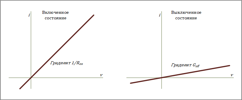
If the voltage on the gate-cathode circuit exceeds that specified in the parameter Threshold voltage, Vth threshold voltage, then the ideal semiconductor switch is in the on state. Otherwise, the switch is in the off state.
When switched on (passes current in the forward direction), the anode-cathode circuit of the switch behaves like a linear resistor with resistance On-state resistance.
In the off state, the anode-cathode circuit of the switch behaves like a linear resistor with low conductivity Off-state conductance.
Using the parameters of the section Integral Diode, you can turn on the protective diode (suppressor). The suppressor protects the semiconductor key by providing a conductive path for the reverse current. An inductive load can create a large reverse voltage surge when a semiconductor switch suddenly turns off the voltage supply to the load.
The table shows the recommended parameter values Integral protection diode depending on the goals.
Goal |
Value for selection |
Block behavior |
Priority of simulation speed. |
|
The block includes an integral copy of the block Diode. To set the parameters of the indoor unit Diode use the parameters Integral Diode. |
Precise setting of charge dynamics in reverse mode. |
|
The block includes an integral copy of the dynamic block model Diode. To set the parameters of the indoor unit Diode use the parameters Integral Diode. |
Ports
Conserving
#
a
—
anode contact
electricity
Details
The electrical port connected to the anode contact of the switch.
| Program usage name |
|
#
k
—
cathode contact
electricity
Details
The electrical port connected to the cathode contact of the switch.
| Program usage name |
|
#
g
—
shutter contact
electricity
Details
The electrical port connected to the gate contact of the switch.
Dependencies
To use this port, set the parameter Gate-control port meaning Electrical.
| Program usage name |
|
Input
#
g
—
shutter contact (output)
scalar
Details
The control signal port connected to the switch gate.
Dependencies
To use this port, set the parameter Gate-control port meaning Signal.
| Data types |
|
| Complex numbers support |
No |
Parameters
Main
#
Gate-control port —
defines the control port: scalar or electric
Signal | Electrical
Details
Scalar or electric gate control port of the switch.
| Values |
|
| Default value |
|
| Program usage name |
|
| Evaluatable |
No |
#
On-state resistance —
resistance in the switched-on state
Ohm | mOhm | kOhm | MOhm | GOhm
Details
The resistance between the anode and the cathode when switched on.
| Units |
|
| Default value |
|
| Program usage name |
|
| Evaluatable |
Yes |
#
Off-state conductance —
conductivity in the off state
S | nS | uS | mS | 1/Ohm
Details
The anode-cathode conductivity is switched off. The value should be less than , where — the value of the resistance when switched on.
| Units |
|
| Default value |
|
| Program usage name |
|
| Evaluatable |
Yes |
#
Threshold voltage, Vth —
Threshold voltage
V | uV | mV | kV | MV
Details
The threshold voltage for the gate-cathode circuit. The switch turns on when the gate-cathode circuit voltage exceeds this value.
| Units |
|
| Default value |
|
| Program usage name |
|
| Evaluatable |
Yes |
Integral Diode
#
Integral protection diode —
internal protective diode (suppressor)
External Diode | Diode with no dynamics | Diode with charge dynamics
Details
Specify whether the unit includes a protective diode (suppressor). The default value is External Diode.
If it is necessary to turn on the internal protective diode, then there are two possible options:
-
Diode with no dynamics. -
Diode with charge dynamics.
| Values |
|
| Default value |
|
| Program usage name |
|
| Evaluatable |
No |
#
Forward voltage —
direct current voltage
V | uV | mV | kV | MV
Details
The minimum voltage required by the + and − ports of the unit in order for the gradient of the volt-ampere characteristic of the diode to be equal to , where — the resistance value on the switched switch.
Dependencies
To use this parameter, set for the parameter Integral protection diode meaning Diode with no dynamics or Diode with charge dynamics.
| Units |
|
| Default value |
|
| Program usage name |
|
| Evaluatable |
Yes |
#
On resistance —
resistance when switched on directly
Ohm | mOhm | kOhm | MOhm | GOhm
Details
The resistance of the diode is in the open state when the voltage is higher than the value set by the parameter Forward voltage.
Dependencies
To use this parameter, set for the parameter Integral protection diode meaning Diode with no dynamics or Diode with charge dynamics.
| Units |
|
| Default value |
|
| Program usage name |
|
| Evaluatable |
Yes |
#
Off conductance —
closed state conductivity
S | nS | uS | mS | 1/Ohm
Details
The conductivity of the diode when it is switched back on.
Dependencies
To use this parameter, set for the parameter Integral protection diode meaning Diode with no dynamics or Diode with charge dynamics.
| Units |
|
| Default value |
|
| Program usage name |
|
| Evaluatable |
Yes |
#
Junction capacitance —
transfer capacity
F | pF | nF | uF | mF
Details
The value of the capacitance characteristic of the transition from the depleted zone, acting as a dielectric and separating the connections of the anode and cathode.
Dependencies
To use this parameter, set for the parameter Integral protection diode meaning Diode with charge dynamics.
| Units |
|
| Default value |
|
| Program usage name |
|
| Evaluatable |
Yes |
#
Peak reverse current, iRM —
peak reverse current
A | pA | nA | uA | mA | kA | MA
Details
The peak return current measured by the external test circuit. This value must be less than zero.
Dependencies
To use this parameter, set for the parameter Integral protection diode meaning Diode with charge dynamics.
| Units |
|
| Default value |
|
| Program usage name |
|
| Evaluatable |
Yes |
#
Initial forward current when measuring iRM —
initial forward current during iRM measurement
A | pA | nA | uA | mA | kA | MA
Details
The initial forward current (at the initial moment of the switch-on time) when measuring the peak reverse current. This value must be greater than zero.
Dependencies
To use this parameter, set for the parameter Integral protection diode meaning Diode with charge dynamics.
| Units |
|
| Default value |
|
| Program usage name |
|
| Evaluatable |
Yes |
#
Rate of change of current when measuring iRM —
the rate of change of current during iRM measurement
A/s | A/us
Details
The rate of change of the current when measuring the peak reverse current. This value must be less than zero.
Dependencies
To use this parameter, set for the parameter Integral protection diode meaning Diode with charge dynamics.
| Units |
|
| Default value |
|
| Program usage name |
|
| Evaluatable |
Yes |
#
Reverse recovery time parametrization —
the method of determining the time of reverse recovery
Specify stretch factor | Specify reverse recovery time directly | Specify reverse recovery charge
Details
Defines the method for setting the reverse recovery time in the block.
When selecting an option Specify stretch factor or Specify reverse recovery charge the value that is used by the block to calculate the reverse recovery time is specified.
Dependencies
To use this parameter, set for the parameter Integral protection diode meaning Diode with charge dynamics.
| Values |
|
| Default value |
|
| Program usage name |
|
| Evaluatable |
No |
# Reverse recovery time stretch factor — the stretching coefficient of the reverse recovery time
Details
The value that the block uses for calculation Reverse recovery time trr. This value should be higher. 1. Specifying the stretching coefficient is an easier way to parameterize the reverse recovery time than specifying the reverse recovery charge. The higher the value of the stretching coefficient, the longer it takes for the reverse recovery current to dissipate.
Dependencies
To use this parameter, set for the parameter Integral protection diode meaning Diode with charge dynamics, and for the parameter Reverse recovery time parametrization set the value Specify stretch factor.
| Default value |
|
| Program usage name |
|
| Evaluatable |
Yes |
#
Reverse recovery time trr —
reverse recovery time
s | ns | us | ms | min | hr | d
Details
The amount of time it takes for a diode to turn off when the voltage across it reverses from forward bias to reverse.
The interval between the moment of the initial transition of the current through zero (when the diode turns off) and the moment the current drops to less than 10% of the peak current. Parameter value Reverse recovery time trr there must be more than the parameter value. Peak reverse current, iRM, divided by the value of the parameter Rate of change of current when measuring, iRM.
Dependencies
To use this parameter, set for the parameter Integral protection diode meaning Diode with charge dynamics, and for the parameter Reverse recovery time parametrization set the value Specify reverse recovery time directly.
| Units |
|
| Default value |
|
| Program usage name |
|
| Evaluatable |
Yes |
#
Reverse recovery charge Qrr —
reverse recovery charge
C | nC | uC | mC | nA*s | uA*s | mA*s | A*s | mA*hr | A*hr | kA*hr | MA*hr
Details
The value that the block uses for calculation Reverse recovery time trr. Use this parameter if the reverse recovery charge value is specified in the block parameters as the type of reverse recovery time determination instead of the reverse recovery time value.
The reverse recovery charge is the total charge that continues to dissipate after the diode is turned off. The value must be less than , where:
-
— the value specified for the parameter Peak reverse current, iRM.
-
— the value specified for the parameter Rate of change of current when measuring iRM.
Dependencies
To use this parameter, set for the parameter Integral protection diode meaning Diode with charge dynamics, and for the parameter Reverse recovery time parametrization set the value Specify reverse recovery charge.
| Units |
|
| Default value |
|
| Program usage name |
|
| Evaluatable |
Yes |